
Stator of an electrical coolant drive, contact device for a stator and electrical coolant drive

Pending Publication Date: 2022-06-16
BROSE FAHRZEUGTEILE SE & CO KGAA WUERZBURG
View PDF0 Cites 0 Cited by
  • Summary
  • Abstract
  • Description
  • Claims
  • Application Information

AI Technical Summary

Benefits of technology

The technical effect of this patent text is to provide a better stator for an electrical coolant drive that can cool the motor and electronics more reliable and safely, especially at low speeds, while also minimizing the pressure loss at high speeds.

Problems solved by technology

However, that relative position of the inlet with respect to the stator disadvantageously induces a substantially frontal impingement of the inflowing fluid or suction gas on the contact device of the stator.
The contact device generally has narrow cross-sections, so that undesired suction pressure losses are induced in that case.
Such suction pressure losses reduce the efficiency of the electrical coolant drive.
In particular in the case of a full-load operation (cool down), an electrical and thermal power limit of the coolant drive is reached in a short time so that the coolant drive has to be limited to prevent damage or total destruction.
However, that is only possible if the outer diameter of the stator can be increased or if the axial length of the drive housing or the coolant drive can be elongated.
However, with regard to the installation space present in an installation situation, that cannot always be readily achieved in technical terms since the other components of the coolant compressor, for example the compressor or the electronics, also require an axial installation space.
However the interconnection of the coils to form the stator winding is thus disadvantageously hindered or limited to certain interconnection patterns / concepts.

Method used


Image

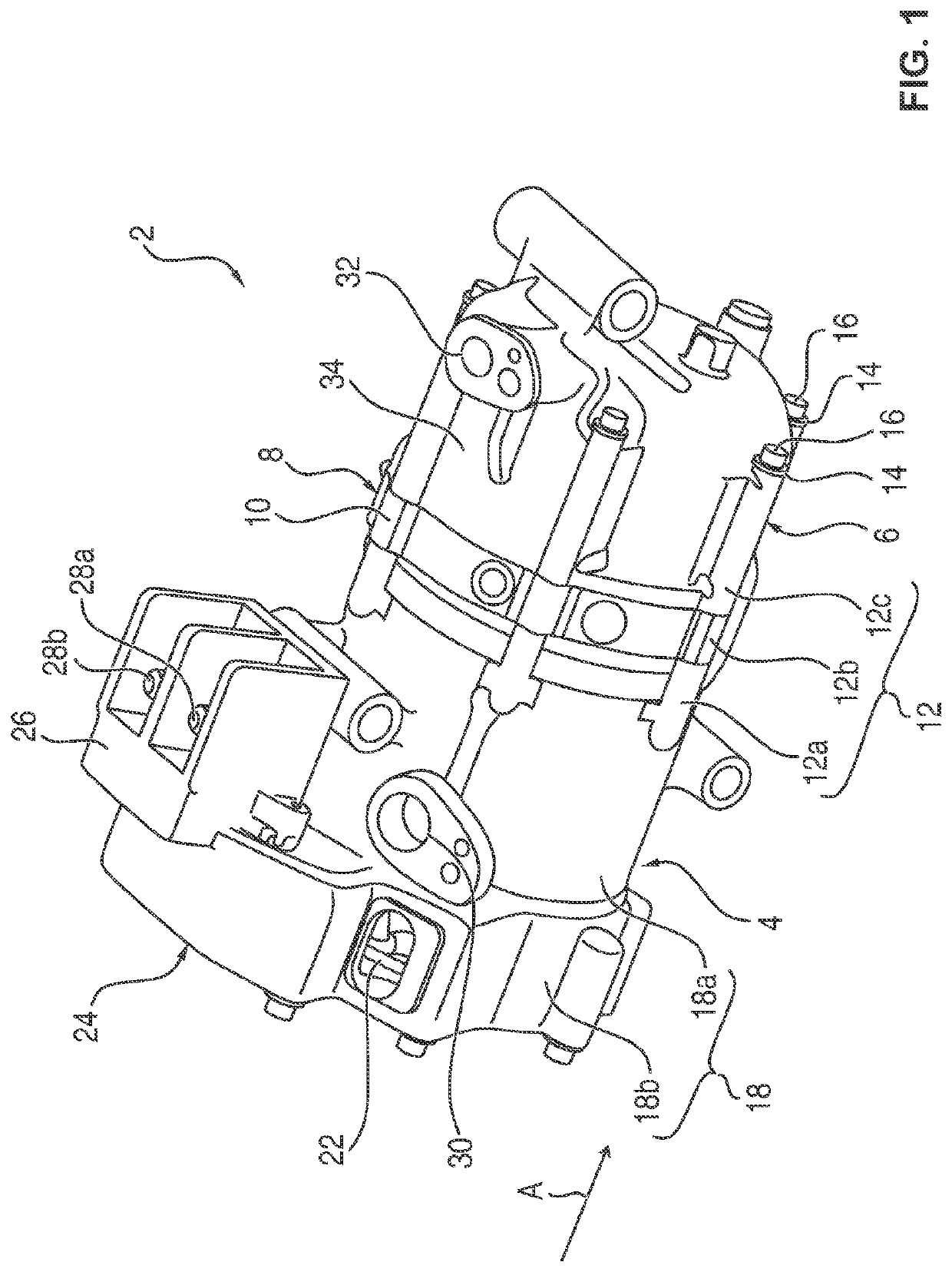
  • Stator of an electrical coolant drive, contact device for a stator and electrical coolant drive
  • Stator of an electrical coolant drive, contact device for a stator and electrical coolant drive
  • Stator of an electrical coolant drive, contact device for a stator and electrical coolant drive

Examples


first embodiment

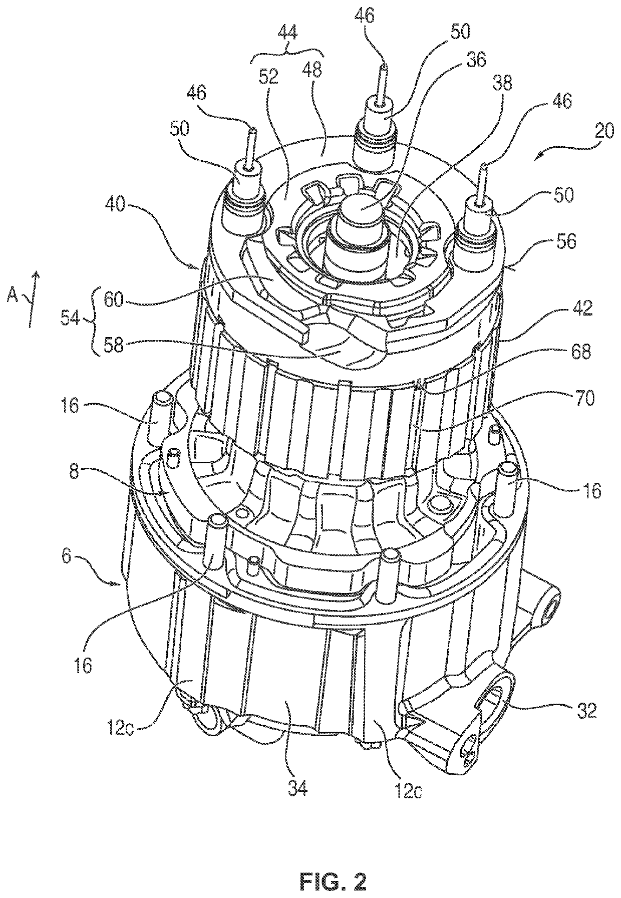
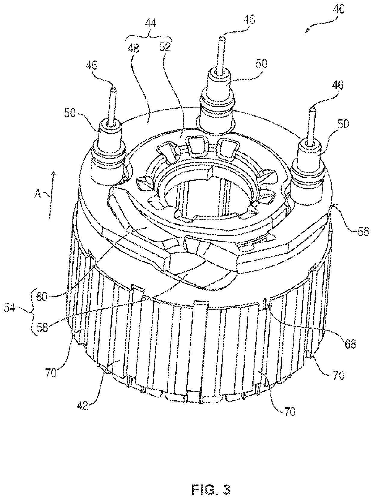
[0064]the contact device 44 is explained in more detail below with reference to FIG. 2 to FIG. 5.

[0065]In this exemplary embodiment, the contact device 44 is constructed in two parts with the radially external, annular base body 48 and a radially internal, annular inner body 52.

[0066]In the base body 48 (also referred to as an interconnection ring below), the coil ends are interconnected and guided to the phase connections 46, wherein the interconnection or contacting of the coil ends of the coils takes place in the radially internal region of the inner body 52 (also referred to as a ring cover below), which is seated on the contacted coil ends as a cover and for protection thereof.

[0067]The contact device 44 has a deflection region 54, which is incorporated as a bead-shaped depression, i.e. as a cutout or indentation, in the outer circumference or periphery 56 of the contact device 44 or the interconnection ring 48. In this case, the deflection region 54 is disposed in the region o...

fourth embodiment

[0084]the contact device 4′″ shown in FIG. 10 corresponds substantially to a six phase embodiment of the above-described contact device 44′ of FIG. 7, in which the deflection region 54′″ is disposed on a tab 72′ of the ring cover 52′″, which tab extends axially and tangentially along the outer edge of the interconnection ring 48′″.


PUM


Abstract

A stator of an electrical coolant drive includes a stator assembly having a number of stator teeth that are provided with coils of a multi-phase stator winding, and a contact device disposed on the stator assembly on an end side for interconnecting the coils with the phase connections. A deflection region is provided on the outer periphery of the contact device in the region of an inlet of the coolant drive for a fluid flowing in through the inlet. A contact device and an electric coolant drive are also provided.

Description

CROSS-REFERENCE TO RELATED APPLICATION[0001]This application is a continuation, under 35 U.S.C. § 120, of copending International Patent Application PCT / EP2020 / 074435, filed Sep. 2, 2020, which designated the United States; this application also claims the priority, under 35 U.S.C. § 119, of German Patent Application DE 10 2019 213 616.8, filed Sep. 6, 2019; the prior applications are herewith incorporated by reference in their entirety.FIELD AND BACKGROUND OF THE INVENTION[0002]The invention relates to a stator of an electrical coolant drive, including a stator assembly having a number of stator teeth, which are provided with coils of a multi-phase stator winding, and a contact device disposed on the stator assembly at the end face. The invention furthermore relates to a contact device for such a stator, and an electrical coolant drive having such a stator.[0003]In motor vehicles, air-conditioning units are generally installed which condition the air in the vehicle interior with th...

Claims


Application Information

Patent Timeline
IPC IPC(8): H02K3/52B60H1/32
CPCH02K3/522H02K2203/09B60H1/3226H02K5/12H02K7/14H02K9/10F04C18/0223F04C23/02F04B35/04F04B39/121F04B39/06H02K15/0062
Inventor PODACK, MARCUSWUEST, STEFANGRIMM, MARCOTONG, DUC VAN
Owner BROSE FAHRZEUGTEILE SE & CO KGAA WUERZBURG
Learn More