Supercharge Your Innovation With Domain-Expert AI Agents!

Precision Time Protocol using a coherent optical DSP frame

a technology of precision time and coherent optical frame, applied in the field of network communication, can solve the problems of time accuracy, non-deterministic timing delay, and difficulty in timing transfer over optical network, and achieve the effect of minimizing delay uncertainty and jitter in timing transfer

Active Publication Date: 2022-06-16
CIENA
View PDF0 Cites 0 Cited by
  • Summary
  • Abstract
  • Description
  • Claims
  • Application Information

AI Technical Summary

Benefits of technology

This patent is about a way to transfer time over optical interfaces using a special structure called a DSP frame. This structure helps to reduce delay and uncertainty in the timing transfer. The patent also describes the use of the DSP frame to transfer time over modems like G.709.3 (FlexO). The technical effect of this patent is to improve the precision and accuracy of timing transfer between optical interfaces.

Problems solved by technology

It does not address performance aspects such as the time accuracy that can be achieved over a network.
These time transfer approaches are protocol-based and do not account for Forward Error Correction (FEC) and DSP mappings in optical networks, causing non-deterministic timing delays.
The transfer of time over optical networks can be challenging because of the delays introduced by elastic First-In-First-Out (FIFOs) required in transport mapping schemes such as OTN and enhanced high coding gain soft-decision Forward Error Correction (SD-FEC) schemes.
Uncertainty in these delays (at start-up or after fault recovery) results in uncertainty in the transferred time.
Also, uncertainty in these delays result in time error between the network nodes.
These complex devices often operate with a gapped clock (data valid), resulting in data path jitter and uncertainty.
All these uncertainties in these delays (at start-up or after fault recovery) results in uncertainty in the transferred time, which is often referred as constant time error (cTE).

Method used


Image

  • Precision Time Protocol using a coherent optical DSP frame
  • Precision Time Protocol using a coherent optical DSP frame
  • Precision Time Protocol using a coherent optical DSP frame

Examples


Embodiment Construction

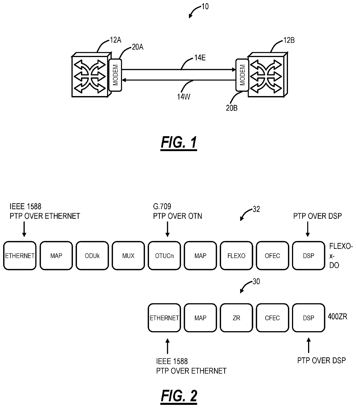
[0017]Again, the present disclosure relates to systems and methods for Precision Time Protocol (PTP) using a coherent Digital Signal Processor (DSP) frame. The present disclosure presents a solution to run PTP (time transfer) over such optical coherent interfaces, using the DSP training symbols as a point of reference for a PTP timestamp. This provides a solution for timing transfer over coherent modems, such as 400ZR, G.709.3 (FlexO), and the like. This can be referred to as PTP over DSP. The objective of the systems and methods is to mitigate and minimize delay uncertainty and jitter in timing transfer between coherent optical interfaces.

Network

[0018]FIG. 1 is a network diagram of an optical network 10 between two nodes 12A, 12B. The nodes 12A, 12B are interconnected by links 14E, 14W providing bidirectional communication. The links 14E, 14W are optical fibers and the nodes 12A, 12B can be network elements, and the nodes 12A, 12B can each include a coherent optical modem 20A, 20B....


PUM


Abstract

A coherent optical modem includes an optical interface; and circuitry connected to the optical interface and configured to detect a first timing reference point in a transmit Digital Signal Processor (DSP) frame in a transmit direction from a first node to a second node, and detect a second timing reference point in a receive DSP frame in a receive direction from the second node to the first node, wherein the first timing reference point and the second timing reference point are determined based on a pattern in any DSP frame field including i) padding area, ii) a reserved area, and iii) a DSP Multi-Frame Alignment Signal (MFAS) area. The pattern can be input in select DSP frames for a time period that is greater than a time period for each DSP frame.

Description

FIELD OF THE DISCLOSURE[0001]The present disclosure generally relates to networking. More particularly, the present disclosure relates to systems and methods for Precision Time Protocol (PTP) using a coherent Digital Signal Processor (DSP) frame.BACKGROUND OF THE DISCLOSURE[0002]Timing synchronization between nodes in a network is described in various standards such as IEEE 1588-2008 “Standard for a Precision Clock Synchronization Protocol for Networked Measurement and Control Systems,” ITU-T G.8265.1 / Y.1365.1 (07 / 14) “Precision time protocol telecom profile for frequency synchronization,” ITU-T G.8275.1 “Time and Phase Profile,” the contents of each is incorporated by reference herein. The requisite information for the transfer of precise time is (1) a timing reference point, or “significant instant” to which timing information can be related, (2) the timing information itself, and (3) a measure of the delay it takes to transfer the timing information between two nodes. IEEE Standa...

Claims


Application Information

Patent Timeline
Patent Type & Authority Applications(United States)
IPC IPC(8): H04J3/06H04J3/16G06F7/58
CPCH04J3/0667G06F7/582H04J3/1652H04J3/0697H04J3/067
Inventor GAREAU, SEBASTIENNICHOLS, JEFFERY THOMASVERGHESE, MANOJMCCARTHY, ANDREW
Owner CIENA
Features
  • R&D
  • Intellectual Property
  • Life Sciences
  • Materials
  • Tech Scout
  • Unparalleled Data Quality
  • Higher Quality Content
  • 60% Fewer Hallucinations
Learn More