
System for lubricating components of a gas turbine engine including a lubricant bypass conduit

Active Publication Date: 2022-06-23
GENERAL ELECTRIC CO
View PDF4 Cites 0 Cited by
  • Summary
  • Abstract
  • Description
  • Claims
  • Application Information

AI Technical Summary

Benefits of technology

The technical effect of this patent is to provide a new invention that has specific improvements and advantages. These improvements can be part of the description of the invention, or they can be found by practicing the invention.

Problems solved by technology

Moreover, the system includes a valve fluidly coupled in series with the scavenge conduit, with the valve being unable to control a flow of the lubricant through the supply conduit.

Method used


Image

  • System for lubricating components of a gas turbine engine including a lubricant bypass conduit
  • System for lubricating components of a gas turbine engine including a lubricant bypass conduit
  • System for lubricating components of a gas turbine engine including a lubricant bypass conduit

Examples


Embodiment Construction

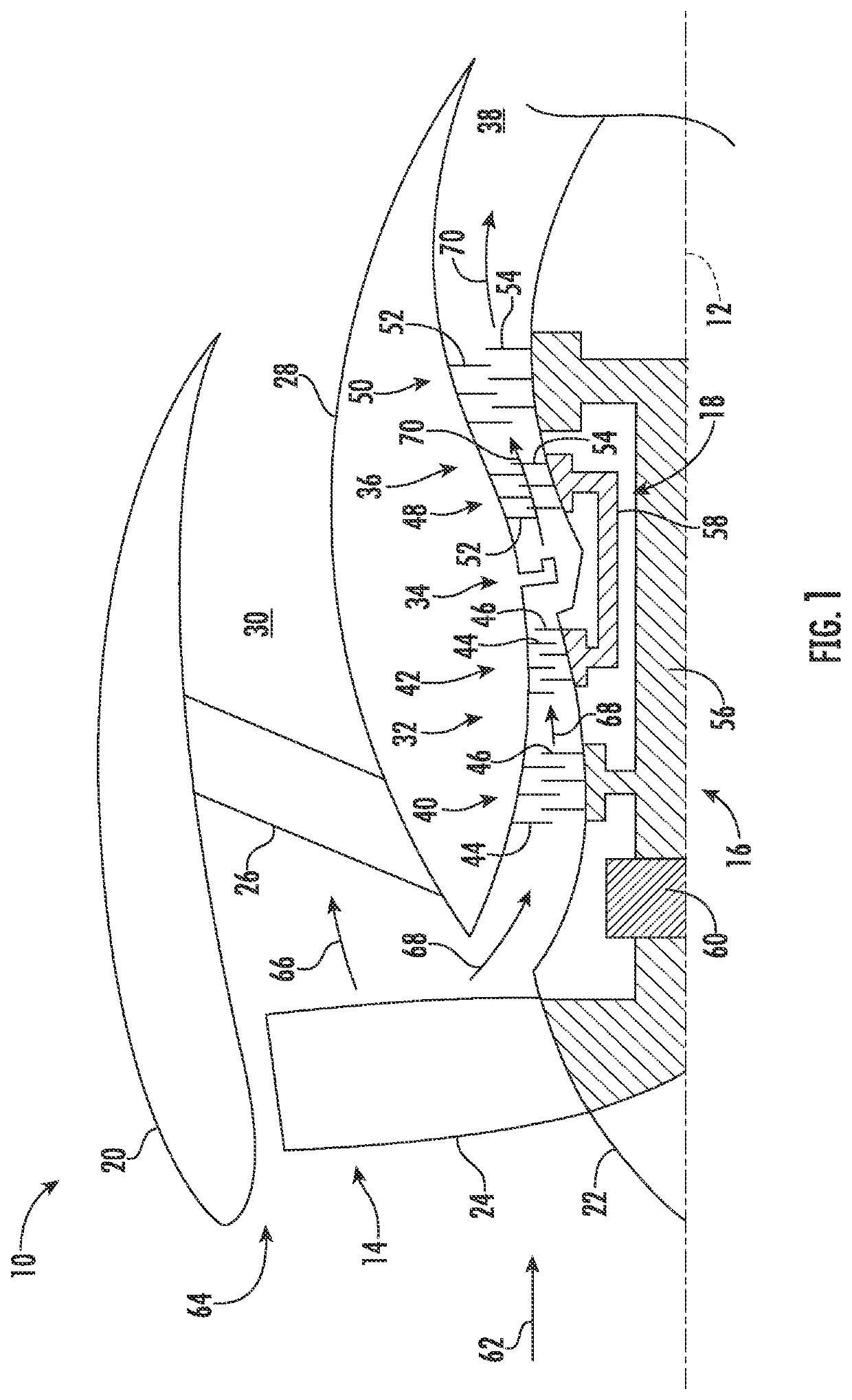
[0017]Reference now will be made in detail to exemplary embodiments of the presently disclosed subject matter, one or more examples of which are illustrated in the drawings. Each example is provided by way of explanation and should not be interpreted as limiting the present disclosure. In fact, it will be apparent to those skilled in the art that various modifications and variations can be made in the present disclosure without departing from the scope or spirit of the present disclosure. For instance, features illustrated or described as part of one embodiment can be used with another embodiment to yield a still further embodiment. Thus, it is intended that the present disclosure covers such modifications and variations as come within the scope of the appended claims and their equivalents.

[0018]As used herein, the terms “first”, “second”, and “third” may be used interchangeably to distinguish one component from another and are not intended to signify location or importance of the i...


PUM


Abstract

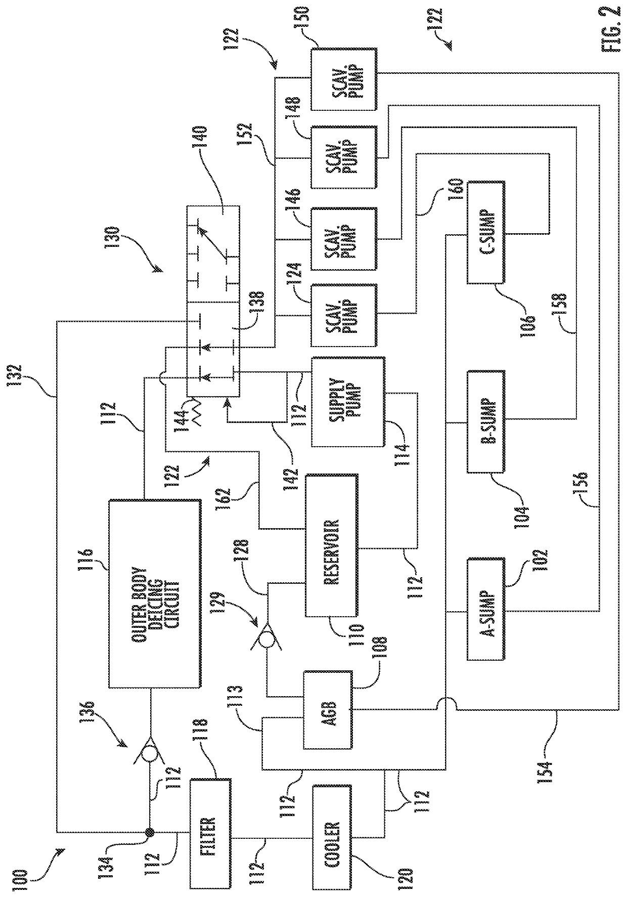
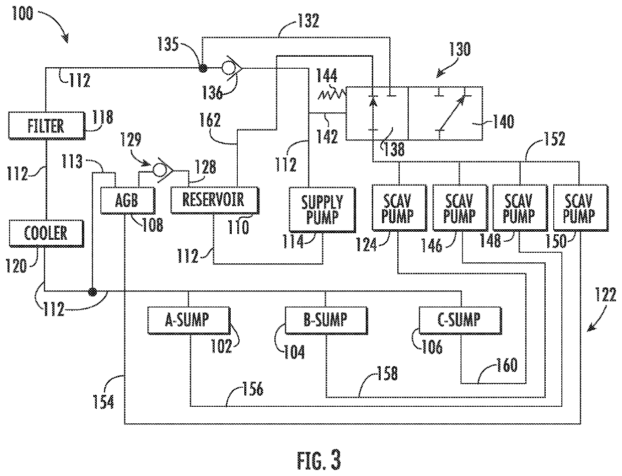
A system for lubricating components of a gas turbine engine includes a supply pump to pump lubricant from a reservoir through a supply conduit to lubricated component. An outer body deicing circuit is fluidly coupled in series with the supply conduit. Moreover, a scavenge conduit extends from the lubricated component to the reservoir and a scavenge pump pumps the lubricant from the lubricated component through the scavenge conduit. In addition, a valve is fluidly coupled in series with the supply conduit and the scavenge conduit and a bypass conduit extends from the valve to a location on the supply conduit downstream of the deicing circuit. When the lubricant is supplied to the valve, the valve directs the lubricant flowing through the scavenge conduit into the reservoir. When the supply of lubricant to the valve is halted, the valve directs the lubricant flowing through the scavenge conduit into the bypass conduit.

Description

FEDERALLY SPONSORED RESEARCH[0001]This invention was made with government support under contract number W58RGZ-16-C-0047 awarded by the U.S. Department of Defense. The government may have certain rights in the invention.FIELD[0002]The present disclosure generally pertains to gas turbine engines, and, more specifically, to a system for lubricating components of a gas turbine engine.BACKGROUND[0003]A gas turbine engine generally includes a compressor section, a combustion section, and a turbine section. During operation, the compressor section progressively increases the pressure of air entering the engine and supplies this compressed air to the combustion section. The compressed air and a fuel mix within the combustion section and burn within a combustion chamber to generate high-pressure and high-temperature combustion gases. The combustion gases flow through a hot gas path defined by the turbine section before exiting the engine. In this respect, the turbine section converts energy...

Claims


Application Information

Patent Timeline
IPC IPC(8): F02C7/06F01D25/20
CPCF02C7/06F01D25/20F05D2240/35F05D2260/98F05D2220/32F02C7/00F01D25/02F02C7/047
Inventor LUZ, JAMES JOHNBROWN, ROBERT BURTONKENNEY, THOMAS BRADLEYMCCARTHY, THOMAS CHARLESYOUNES, FIRAS
Owner GENERAL ELECTRIC CO
Learn More