Unit cell, and method and apparatus for manufacturing same

a technology of unit cells and cells, applied in the field of unit cells, can solve the problems of damage or movement of the positive and negative electrodes, and achieve the effects of accurate position, optimal bonding state, and damage to the negative electrod

Pending Publication Date: 2022-06-23
LG ENERGY SOLUTION LTD
View PDF0 Cites 0 Cited by
  • Summary
  • Abstract
  • Description
  • Claims
  • Application Information

AI Technical Summary

Benefits of technology

[0039]In the method for manufacturing the electrode assembly according to the present invention having the above-described technical features, because the heat and pressure may not or need not be applied or may be applied much weaker than the related art when the electrode and the separator are laminated, the distortion between the separator and the electrode may be prevented, and the deformation of the electrode and the separator, the damage thereto, and the like may be prevented.
[0040]In the present invention, according to the application position of the adhesive, the separators are bonded to each other, or the separator is bonded to the electrode, whereby the electrode may be fixed. That is, according to the properties of the electrode such as size and thickness, the adhesive is applied to the region to which the electrode is mounted, and thus the separator may directly fix and prevent the electrode from moving, or the separators stacked on both sides of the electrode are bonded to each other, whereby the electrode may be prevented from moving.
[0041]In addition, since the adhesive may be partially applied to only very small regions such as the corners of the electrode in the manufacturing method of the present invention, when this method is additionally applied to the lamination process of the related art in which the heat and pressure are applied, the position of the electrode may be temporarily fixed before the lamination process is conducted.
[0042]In the present invention, the adhesive is ejected in the form of small particles and thus may be dispersed and impregnated between coating layers on the surface of the separator.
[0043]Also, since the electrodes (the positive electrode, the negative electrode) may be input through the visions and the grippers, the electrode may be input and mounted to more accurate position compared to the method in which a cutting speed of a cutter is controlled.
[0044]In addition, since the application amount may be controlled in a specific region of the unit cell according to the present invention, the optimal bonding state may be provided according to the usage of the unit cell and the characteristics of the separator and the electrode.

Problems solved by technology

However, in the method according to the related art described above, the electrodes (the positive and negative electrodes) may be moved away from original right positions or damaged while being heated and pressed.

Method used


Image

  • Unit cell, and method and apparatus for manufacturing same
  • Unit cell, and method and apparatus for manufacturing same
  • Unit cell, and method and apparatus for manufacturing same

Examples


first embodiment

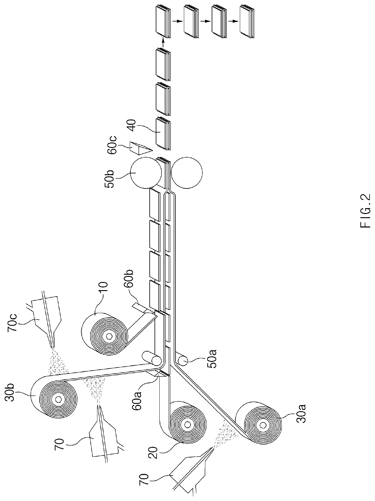
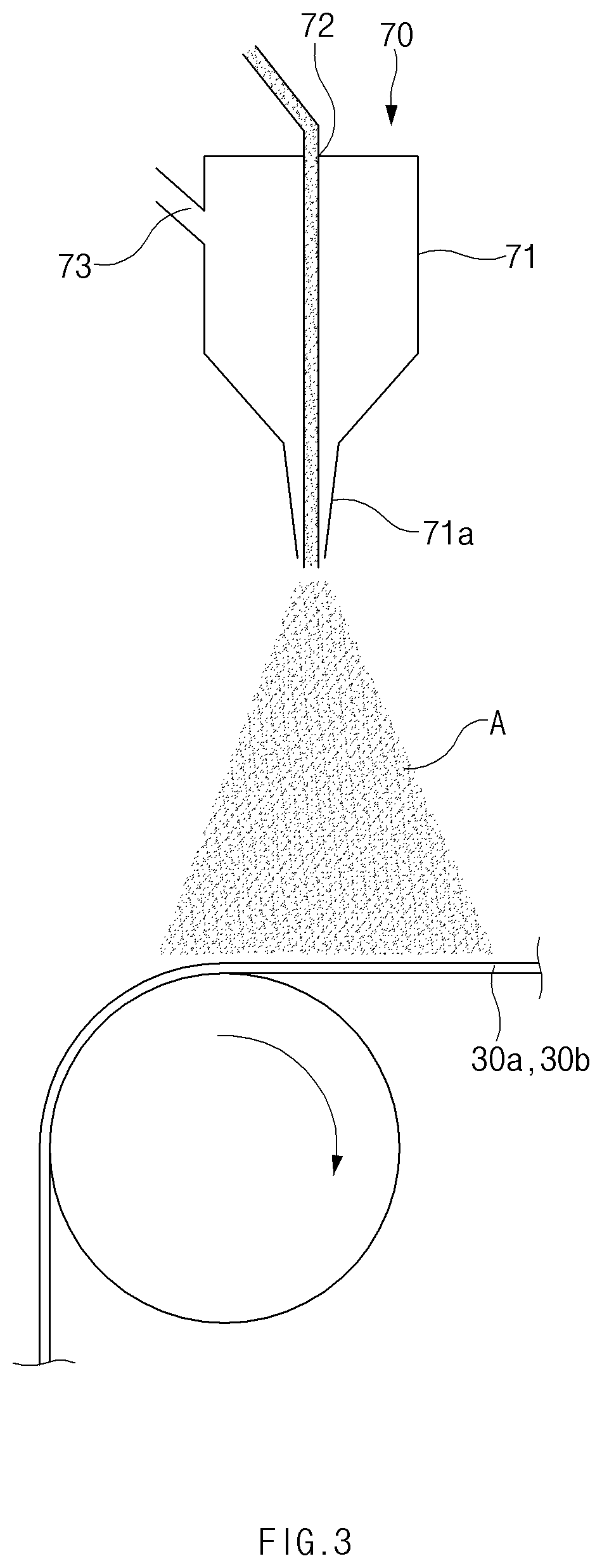
[0062]FIG. 2 is a view schematically illustrating a state in which manufacturing is being carried out through a manufacturing method according to a first embodiment of the present invention, FIG. 3 is a view schematically illustrating a state in which an adhesive is sprayed in the form of mist, and FIG. 4 is a view schematically illustrating a state in which an adhesive is sprayed in the form of droplets. Also, FIG. 5 is a view illustrating a state in which an adhesive is impregnated into a surface of a coating layer of a separator, and FIG. 6 is a view illustrating positions (a) to (f) in which an adhesive may be applied with respect to an electrode.

[0063]A method for manufacturing a unit cell provided in the embodiment comprises an adhesive applying step, an electrode inputting step, and the stacking step. Also, the unit cell has a structure in which a certain number of a negative electrode 20, a separator 30, and a positive electrode 10 are stacked repeatedly.

[0064]First, in the ...

second embodiment

[0087]As a second embodiment, the present invention provides a manufacturing method in which an electrode may be input more accurately, and an adhesive A may be applied more precisely in the vertical direction (that is, from the top to the bottom) so that a spray direction is not affected by gravity.

[0088]FIG. 7 is a view schematically illustrating a state in which a unit cell is being manufactured through a manufacturing method according to the second embodiment of the present invention by a manufacturing apparatus according to a third embodiment described later, FIG. 8 is a view schematically illustrating a state when the state of FIG. 7 is viewed from the side, and FIG. 9 is a view schematically illustrating a state when the state of the FIG. 7 is viewed from the top to the bottom.

[0089]Similar to the manufacturing method of the first embodiment, the manufacturing method of the embodiment also provides a method for manufacturing a unit cell 40 by stacking an electrode 10 and sepa...

third embodiment

[0097]As a third embodiment, the present invention provides a manufacturing apparatus capable of performing the manufacturing method according to the second embodiment.

[0098]Referring to FIGS. 7 to 9, an apparatus for manufacturing a unit cell according to the embodiment comprises: a lower reel from which a lower separator 30a located at a relatively lower position is unwound; a first nozzle 70a which applies an adhesive to at least a portion of a top surface, facing upward, of the unwound lower separator 30a; an upper reel from which an upper separator 30b located at a relatively upper position is unwound; a second nozzle 70b which applies an adhesive to at least a portion of one surface, facing upward, of the unwound upper separator 30b; a guide roller 51 which changes the conveyance direction of the upper separator 30b so that the upper separator 30b unwound from the upper reel passes horizontally under the second nozzle 70b; and a nip roller 50a which inputs the upper separator ...


PUM

PropertyMeasurementUnit
spray anglesaaaaaaaaaa

Abstract

Discussed is method for manufacturing a unit cell in which a certain number of separators and electrodes are alternately stacked, the method including: an adhesive applying operation of continuously providing a lower separator at a relatively lower position and an upper separator at a relatively upper position and applying an adhesive to a surface of at least one separator of the lower separator or the upper separator; an electrode inputting operation of inputting an electrode onto the lower separator; and a stacking operation of positioning and stacking the electrode between the lower separator and the upper separator. The adhesive applied on the at least one separator allows the electrode to be bonded to the at least one separator or allows the other separator to be bonded to the at least one separator, thereby preventing the electrode from moving relative to at least one of the upper and lower separators.

Description

CROSS-REFERENCE TO RELATED APPLICATION[0001]The present application claims the benefit of the priority of Korean Patent Application No. 10-2019-0164069, filed on Dec. 10, 2019 and Korean Patent Application No. 10-2020-0151975, filed on Nov. 13, 2020, which are hereby incorporated by reference in their entirety.TECHNICAL FIELD[0002]The present invention relates to a unit cell and a method and apparatus for manufacturing the same and, more specifically, to: a unit cell in which electrodes (a negative electrode, a positive electrode) are bonded to a separator using an adhesive unlike a lamination method using heat and pressure according to the related art, thereby preventing the electrodes and the separator from moving; and a method and apparatus for manufacturing the same.BACKGROUND ART[0003]Secondary batteries are rechargeable unlike primarily batteries, and also, the possibility of compact size and high capacity is high. Thus, recently, many studies on secondary batteries are being ...

Claims


Application Information

Patent Timeline
Patent Type & Authority Applications(United States)
IPC IPC(8): H01M10/04
CPCH01M10/0468Y02P70/50Y02E60/10H01M10/0404H01M50/461
Inventor BAE, SANG HOJUNG, SU TAEKKWON, SOON KWANCHOI, SEONG WONLEE, YONG JUNLEE, SANG WOOHWANG, WON PILLKIM, TAE JONG
Owner LG ENERGY SOLUTION LTD
Why Eureka
Try Eureka