Optical pickup and disc drive using optical pickup
a technology of optical pickups and disc drives, applied in the manufacture of optical heads, instruments, data recording, etc., can solve the problems of thermal stress and inclination of optical parts, and achieve the effect of suppressing the distortion of a case in accordance with the change of environmental temperature, preventing parts from falling out and/or damage to the cas
- Summary
- Abstract
- Description
- Claims
- Application Information
AI Technical Summary
Benefits of technology
Problems solved by technology
Method used
Image
Examples
embodiment 1
[0029]Prior to the explanation of the embodiments of the present invention, the structure of a general optical pickup will be described.
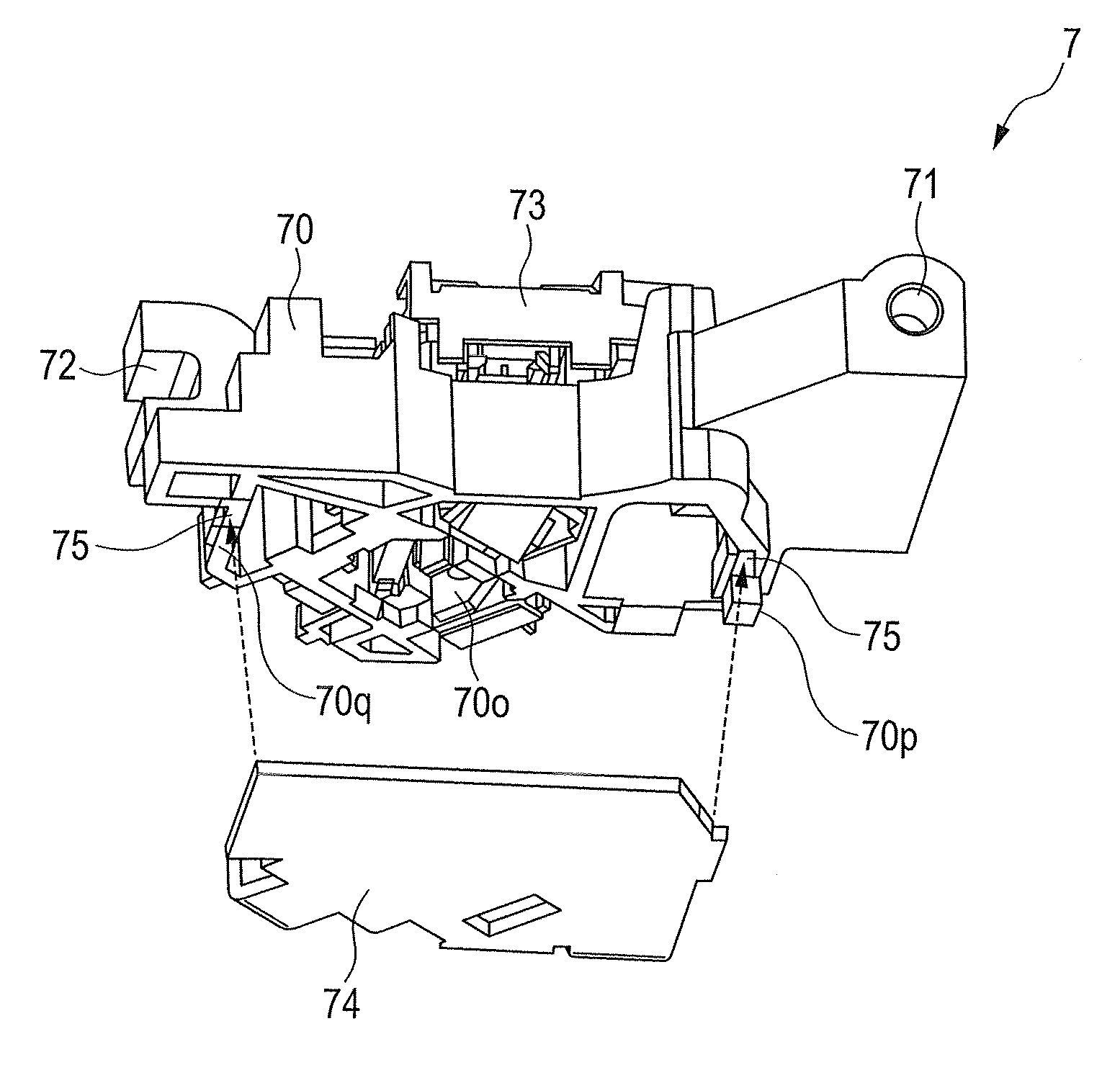
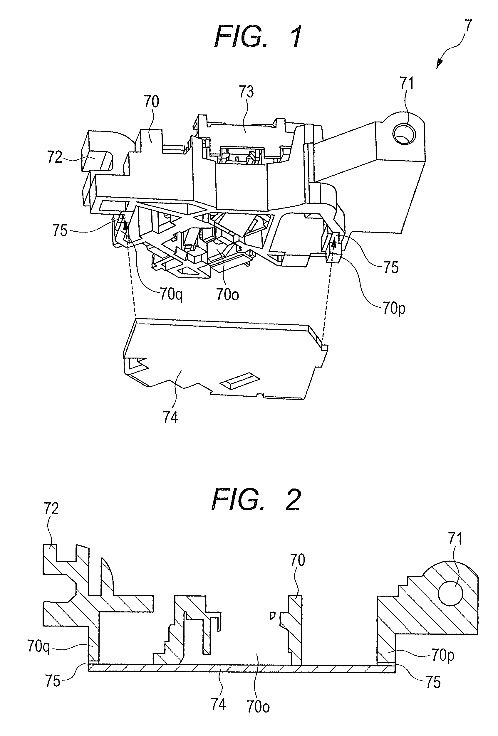
[0030]FIG. 1 is an exploded perspective diagram of a general optical pickup.
[0031]FIG. 2 is a cross-sectional diagram showing positional relation between a case and a metal plate in the general optical pickup.
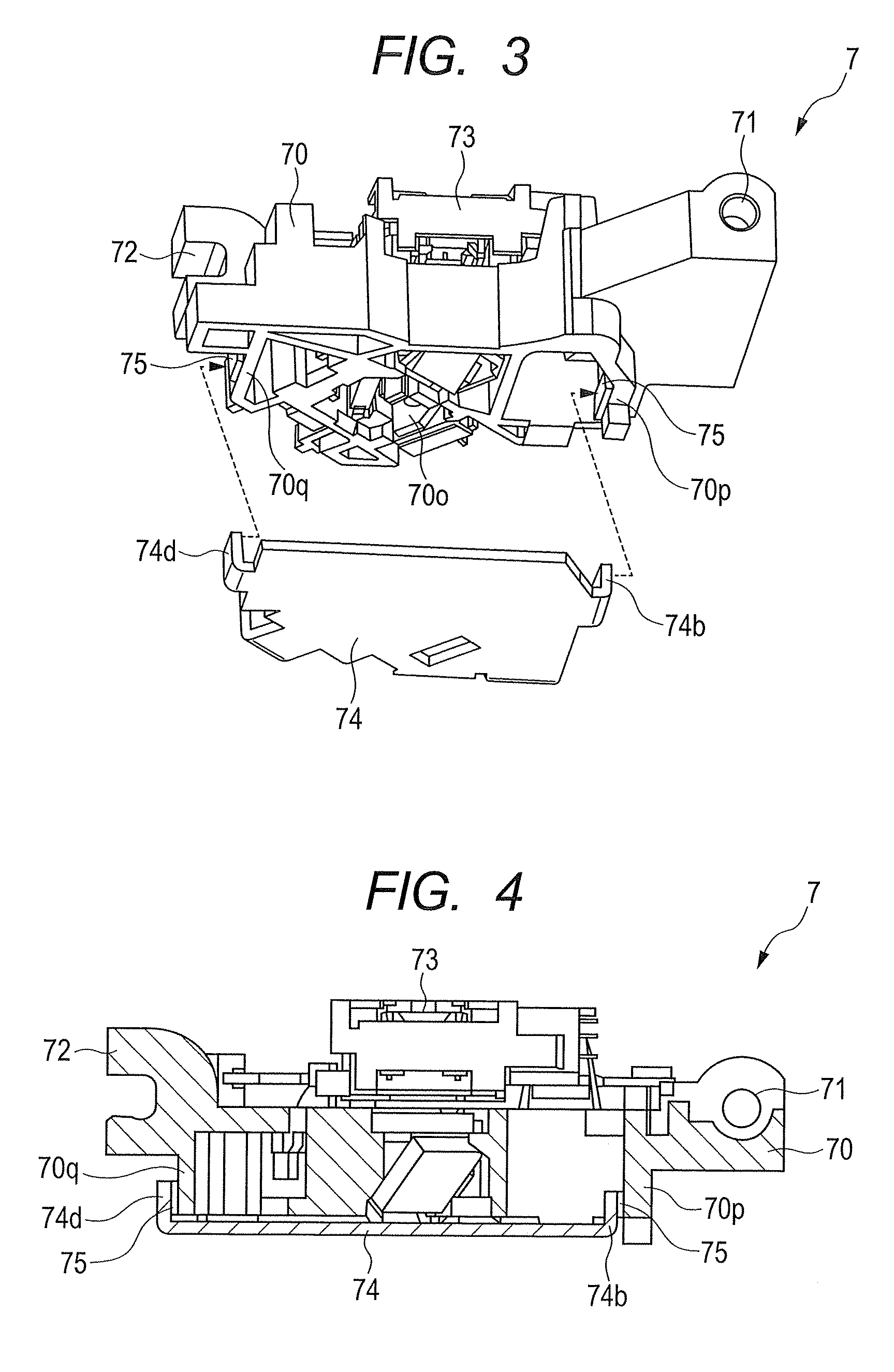
[0032]An optical pickup 7 is a device to write / read information on / from a disc. In FIG. 1, the optical pickup 7 mainly has three elements, i.e., an object lens actuator 73, an optical system and a circuit board (not shown). The optical system has a laser diode as a light source, an optical part to focus laser light from the laser diode on a recording surface of the disc or to generate / detect a control error signal, a photo-detector to convert variation of reflection light from the disc into an electric signal, and the like. The object lens actuator 73 drives an object lens in a focusing direction and a tracking direction, to bring a focal point...
embodiment 2
[0063]FIG. 8 is an exploded perspective diagram of the optical pickup according to an embodiment 2 of the present invention.
[0064]In FIG. 8, in the present embodiment, an opening 74o is provided at the root of the rising member 74b in the two rising members 74b and 74d of the metal plate 74. The rising member 74b is fixed to the surface A′ of the wall 70q of the case with the adhesives 75 at the surface B from which the normal vector extends toward the inside of the optical pickup 7.
[0065]That is, in the present embodiment, in addition to the advantage described in the embodiment 1, it is possible to perform the application of the adhesives 75 to fix the metal plate 74 to the case 70 and the hardening by UV light irradiation through the opening 74o from one direction indicated with an arrow E in the figure, to improve the workability upon assembling.
[0066]Note that in the present embodiment, the opening 74o is provided at the root of the rising member 74d of the metal plate 74, howe...
embodiment 3
[0067]FIG. 9 is an exploded perspective diagram of a disc drive 1 to which the optical pickup 7 of the present invention is applied.
[0068]In FIG. 9, the disc drive 1 mainly has a mechanical base 2, a loading mechanism to load a disc (not shown) into the drive and unload the disc to the outside of the drive, a controller 6 to drive-control the electronic part installed in the disc drive 1 and perform signal processing, a read-write mechanism to read / write information from / to the disc, and the like.
[0069]In the mechanical base 2, its upper surface and side surfaces are covered with a top cover 11 and a lower surface is covered with an under cover 12. The loading mechanism has a disc tray 14 to hold the disc when the disc is carried in into the mechanical base 2 or carried out from the mechanical base 2, a carrying-in / carrying-out mechanism to carry in the disc inside the mechanical base 2 and place the disc on a turn table of a spindle motor 5, and a vertical driving mechanism to move...
PUM
| Property | Measurement | Unit |
|---|---|---|
| reflection | aaaaa | aaaaa |
| optical | aaaaa | aaaaa |
| molding workability | aaaaa | aaaaa |
Abstract
Description
Claims
Application Information
 - R&D
- Intellectual Property
- Life Sciences
- Materials
- Tech Scout
- Unparalleled Data Quality
- Higher Quality Content
- 60% Fewer Hallucinations
Browse by: Latest US Patents, China's latest patents, Technical Efficacy Thesaurus, Application Domain, Technology Topic, Popular Technical Reports.
© 2025 PatSnap. All rights reserved.Legal|Privacy policy|Modern Slavery Act Transparency Statement|Sitemap|About US| Contact US: help@patsnap.com


