Method for precisely detecting a signal for example of a sensor

a technology for precisely detecting signals and sensors, applied in the field of precisely detecting signals for example of sensors, can solve problems such as slow methods

Pending Publication Date: 2022-06-23
ROBERT BOSCH GMBH
View PDF0 Cites 0 Cited by
  • Summary
  • Abstract
  • Description
  • Claims
  • Application Information

AI Technical Summary

Benefits of technology

[0021]The effect on which the present invention is based, i.e. that the modifications explained above at least partly mutually compensate one another in the calculation of the measurement value corrected with regard to offset and gain from the digital values, is present to a particularly high degree when the evaluation and control unit is brought into the same initial state before each individual measurement. For this purpose, it can be provided that individual, or all, energy storage devices, functional values, digital memories, and / or functional blocks of the evaluation and control unit are reset before each individual measurement, to an identical, defined, but not necessarily stationary initial state.
[0022]The effect on which the present invention is based, i.e., that the modifications explained above at least partly mutually compensate one another in the calculation of the measurement value corrected with regard to offset and gain from the digital values, is also present to a particularly high degree when individual measurements have an identical timing relative to one another; i.e., in particular that immediately preceding these measurements, identical measurements, or other measurements of the same type, with the evaluation and control unit take place with the same temporal spacing; and / or when the switches of the multiplexer have a precise matching to one another; i.e. in particular that in the closed state these switches have identical resistance values, and that in the open state these switches have identical resistance values and / or that the switching times of these switches are identical. The concept of identity here includes only a fairly narrow range of fluctuation, for example plus / minus 2%.

Problems solved by technology

These methods are correspondingly slow.

Method used


Image

  • Method for precisely detecting a signal for example of a sensor
  • Method for precisely detecting a signal for example of a sensor

Examples


Embodiment Construction

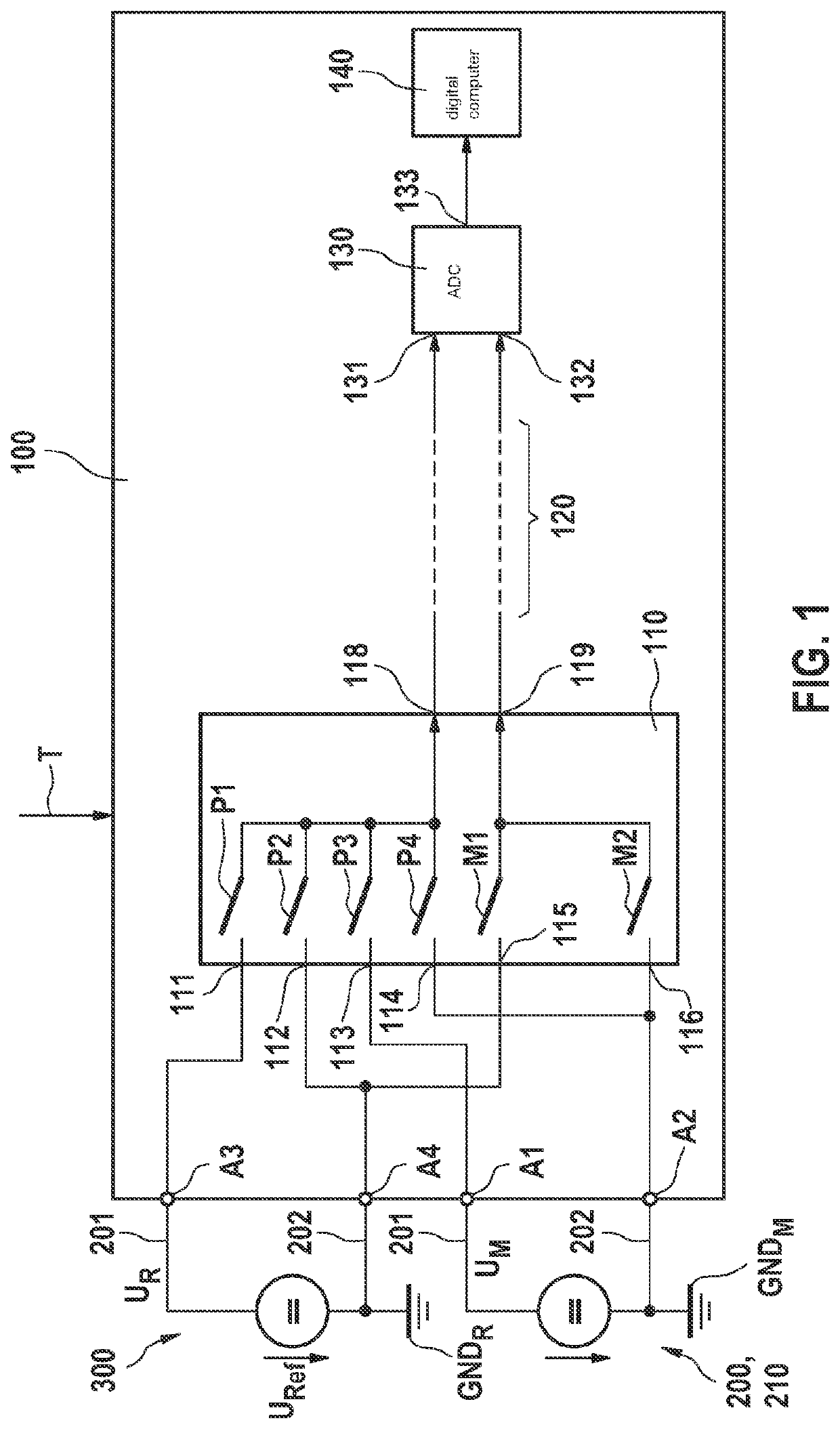
[0027]FIG. 1 shows an evaluation and control unit 100 for operating a broadband lambda sensor 200. Evaluation and control unit 100 is connected to electrical lines 201, 202 of a broadband lambda sensor 200 via terminals, of which only two terminals A1, A2 are shown in FIG. 1. These lines 201, 202 lead for example to an electrochemical cell 210 of broadband lambda sensor 200, so that at the sensor there are a measurement value UM of broadband lambda sensor 200, and its ground potential GND_M. Evaluation and control unit 100 is connected to a reference voltage source 300 and its ground potential GND_R via two further terminals A3, A4. Alternatively, reference voltage source 300 and its ground potential GND_R could also be part of evaluation and control unit 100. The actual value URef of the voltage provided by reference voltage source 300 is known very accurately and in addition is temporally constant.

[0028]Possible details of broadband lambda sensor 200 are presented for example in G...


PUM

PropertyMeasurementUnit
voltageaaaaaaaaaa
timeaaaaaaaaaa
offset voltageaaaaaaaaaa

Abstract

A method for precise acquisition of a signal of a sensor, by an evaluation and control unit which has a multiplexer at whose inputs there is at least one reference voltage whose voltage value is known, a ground potential of the reference voltage, a measurement signal of the exhaust gas sensor, and a ground potential of the measurement signal. A computer is connected downstream from the multiplexer via a transmission path and via an ADC that converts a voltage between its two inputs into a digital value. The method provides that a plurality of individual measurements are carried out in which switching states of the multiplexer are modified, and digital values are subsequently acquired at the output of the ADC. The computer calculates a measurement value, corrected with regard to offset and gain, from these digital values.

Description

BACKGROUND INFORMATION[0001]From the related art, methods are available with which an analog signal is transmitted along a transmission path and subsequently digitized, occurrent offset and gain errors being corrected. In these methods, it is always presupposed that the transmitted signals that are to be digitized are temporally constant, i.e., are in a settled state, so that a measurement value free of offset and gain errors can easily be obtained from the analog signal; see for example U.S. Pat. No. 7,710,303 B2. These methods are correspondingly slow.SUMMARY[0002]The present invention is based on the surprising finding by the inventors that, in a method in accordance with the present invention, measurement values that are corrected with regard to offset and gain can also be determined without the two levels at the inputs of the ADC (analog-digital converter) having settled for each individual measurement.[0003]It is true that, in particular, each of the digital values obtained th...

Claims


Application Information

Patent Timeline
Patent Type & Authority Applications(United States)
IPC IPC(8): H03M1/06G01N27/12
CPCH03M1/0609G01N27/122H03M1/1028H03M1/122
Inventor BAUMANN, FABIANLEDERMANN, BERNHARDBEVOT, CLAUDIUSMEZGER, FLORIAN
Owner ROBERT BOSCH GMBH
Why Eureka
Try Eureka