Dipole loudspeaker for producing sound at bass frequencies

a bass frequency and loudspeaker technology, applied in the direction of transducer diaphragms, loudspeakers, electromechanical transducers, etc., can solve the problems of difficult to keep inside a room, difficult to package a mid-high frequency loudspeaker in combination with a bass frequency loudspeaker in a limited space, and a personal sound cocoon at mid and high frequencies

Pending Publication Date: 2022-06-30
PSS BELGIUM
View PDF6 Cites 0 Cited by
  • Summary
  • Abstract
  • Description
  • Claims
  • Application Information

AI Technical Summary

Benefits of technology

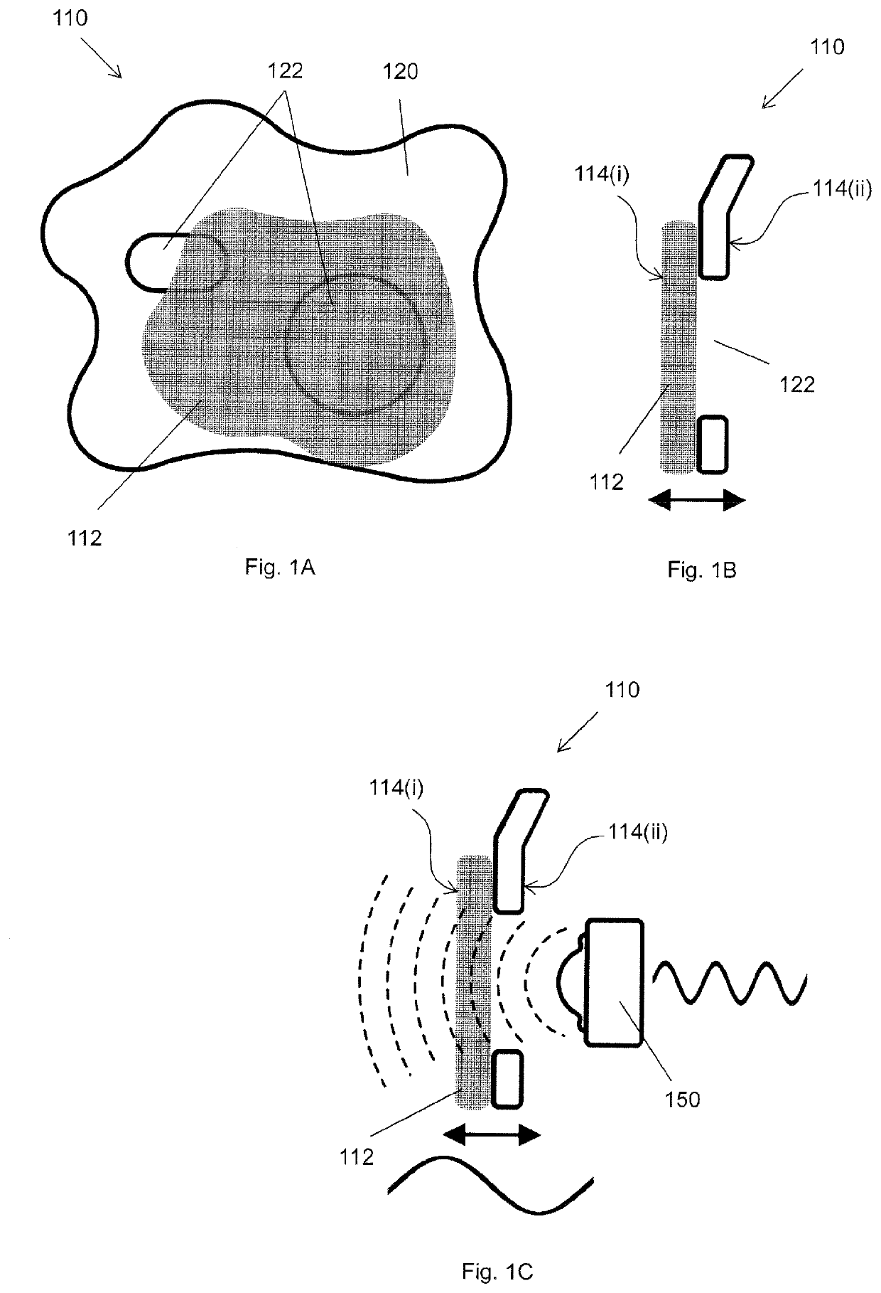
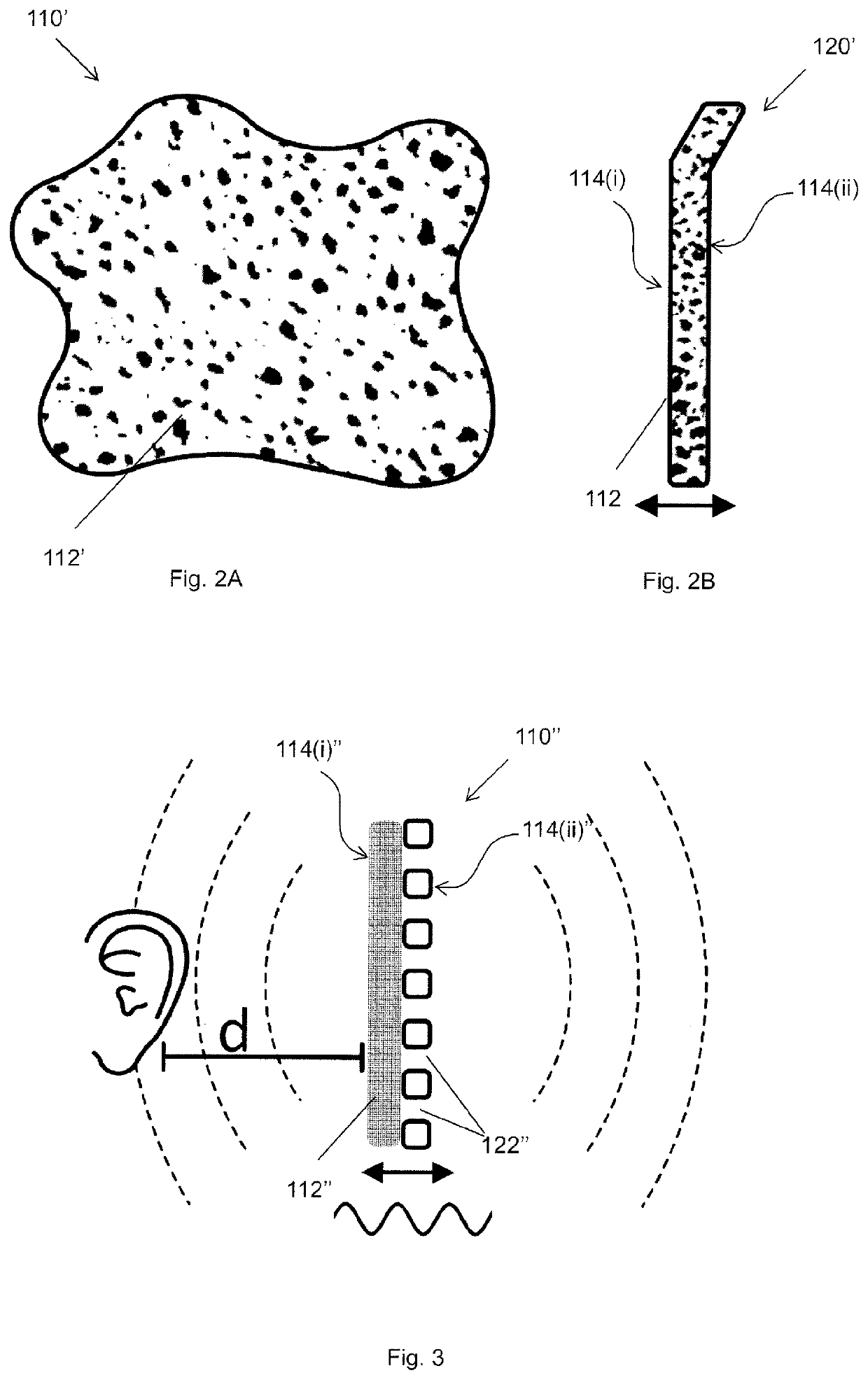
[0026]The present inventors have observed that configuring the diaphragm to permit airflow through at least part of a region of porous material having a specific airflow resistance in the stated range helps the dipole loudspeaker to produce sound at bass frequencies with a similar performance to a non-porous diaphragm.
[0027]The diaphragm of such a dipole loudspeaker cam also exhibit excellent sound absorption qualities for mid and high frequencies, since the (at least part of) the region of porous material through which air can flow will allow mid and high frequencies to pass through, thereby allowing for much more friction at the velocity maxima of these sound waves. This is in contrast with a diaphragm having a non-porous reflective surface covered with a layer porous material of the same thickness.
[0028]Note that when such a dipole loudspeaker is used in close proximity to an ear of the user, the (at least part of) the region of porous material through which air can flow will sound more quiet to the user in the mid and high frequencies due to the improved absorption of mid and high frequencies, thus making the loudspeaker particularly useful for creating a personal sound cocoon.
[0029]Also, such a dipole loudspeaker can beneficially be used in a configuration in which a mid-high frequency loudspeaker, e.g. with the mid-high frequency loudspeaker located behind the (at least part of) the region of porous material through which air can flow, thereby improving packaging options. This possibility is discussed in more detail below.
[0041]If the diaphragm includes a layer of porous material mounted on a supporting structure, the face of the diaphragm on which the layer of porous material is mounted preferably provides the first radiating surface of the diaphragm, and the opposite face of the diaphragm preferably provides the second radiating surface of the diaphragm. Thus, if the dipole loudspeaker is configured for use with an ear of a user located at a listening position that is in front of the first radiating surface of the diaphragm (see above), the face of the diaphragm on which the layer of porous material is mounted preferably faces the ear of the user. This helps to maximise the effectiveness of the personal sound cocoon provided to the user in the mid-high frequency range.

Problems solved by technology

Among the frequencies in the audible spectrum, lower frequencies are the ones that tend to carry most well over larger distances and are the ones difficult to keep inside a room.
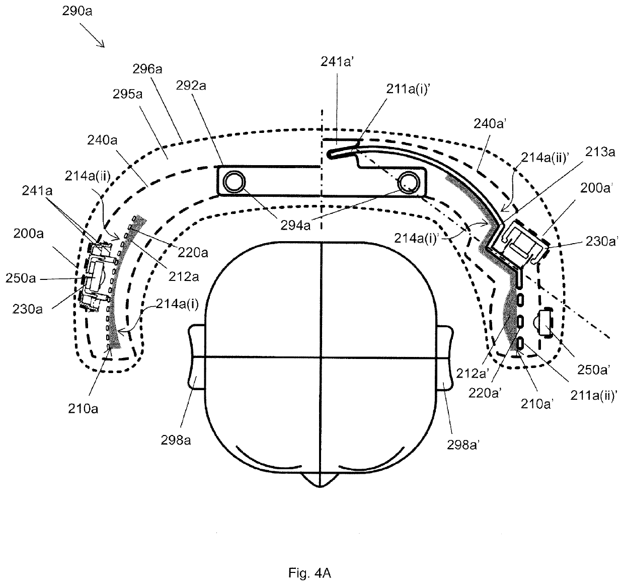
However, packaging a mid-high frequency loudspeaker in combination with a bass loudspeaker is challenging in a limited space such as a seat headrest, especially when it is considered that the diaphragm of the bass loudspeaker(s) need to have a large radiating surface to permit enough volume displacement for adequate low frequency reproduction, as explained for example in PCT / EP2018 / 084636.
Thus, when such a diaphragm is used in close proximity to a mid-high frequency loudspeaker, the solid non-porous diaphragm behaves like a reflective surface, scattering the arriving soundwaves at mid-high frequencies back into the local environment, hence jeopardizing a personal sound cocoon at mid and high frequencies.
However, the absorption provided by such a layer of absorbent material is limited by the available thickness of the layer, yet in most cases (and particularly if a loudspeaker is to be mounted in close proximity to an ear of a user) it is inconvenient to apply a layer of absorbent material having a large thickness to the outer surface of the solid non-porous diaphragm, due to the lack of available space.
So in practice, the method of covering a solid non-porous diaphragm of a bass loudspeaker with a layer of absorbent material may only help to absorb sound energy at mid-high frequencies in a very limited way, e.g. at very high frequencies only.

Method used


Image

  • Dipole loudspeaker for producing sound at bass frequencies
  • Dipole loudspeaker for producing sound at bass frequencies
  • Dipole loudspeaker for producing sound at bass frequencies

Examples


experiment 1

[0170]FIG. 6A shows an experimental apparatus used for experiment 1.

[0171]The experimental apparatus included a diaphragm 410 that included includes a layer 412 of porous material mounted on a supporting structure 420.

[0172]The layer 412 of porous material was 10 mm Basotect open cell foam.

[0173]Basotect is a trademark from BASF and is an open cell melamine foam with a well-defined flow resistivity of approximately 10 kPa·s / m2. Therefore, it is often used as a reference open cell foam.

[0174]The supporting structure 420 was a 2 mm thick aluminium perforated plate having circular holes of diameter 5 mm arranged with a distance of 8 mm centre to centre (see inset circle). The aluminium plate was 32 cm in length, 20 cm wide, and was excited at a nodal line 25 cm from its base via a voice coil 437 mounted to a voice coil former 438 attached to the with a grounded magnet unit 432.

[0175]Note: the perforated plate used here is so open in structure, its specific airflow resistance that is cl...

experiment 2

[0184]FIG. 7 shows an experimental apparatus used for experiment 2.

[0185]The experimental apparatus used here is the same as for experiment 1, except that an additional supplementary mid-high frequency loudspeaker 450 was mounted to produce sound which propagates through a part of the layer 412 of porous material that airflow is permitted to flow through via the perforated plate 420.

[0186]In this experiment, the diaphragm 410 and supplementary loudspeaker 450 were used to play sound in the bass and mid-high frequencies (respectively), with a person locating their ear so that they could listen to sound produced by the mid-high frequency loudspeaker after this sound had propagated through the layer 412 of porous material (and the supporting structure 420) of the diaphragm 410.

[0187]The person listening to this sound reported that the sound was great, that the sound produced in the mid-high frequencies was perceived to be audibly non-affected by the diaphragm 410 and that this sound ac...

experiment 3

[0188]FIG. 8A shows an experimental apparatus used for experiment 3.

[0189]The experimental apparatus used here is the same as for experiment 1, except that a different perforated plate 420′ was used, as shown by the inset rectangle. Here the perforated plate 420′ used was 3 mm thick hardboard with irregularly spaced circular holes having a 55 mm diameter.

[0190]The plate was again 32 cm in length and 20 cm wide.

[0191]Note: the perforated plate 420′ used here allows airflow through the parts of the layer 412 of porous material located over and close to the holes, though there may be some parts of the layer 412 (e.g. which are located far away from the holes) through which airflow is not permitted by the perforated plate 420′.

[0192]The use of perforated plate 420′ was intended to demonstrate that a perforated plate with densely packed small holes are not required to obtain good results, and that good results can still be obtained with very large holes that provide little support and wh...


PUM


Abstract

A dipole loudspeaker for producing sound at bass frequencies. The dipole loudspeaker includes: a diaphragm having a first radiating surface and a second radiating surface, wherein the first radiating surface and the second radiating surface are located on opposite faces of the diaphragm; a drive unit configured to move the diaphragm at bass frequencies such that the first and second radiating surfaces produce sound at bass frequencies, wherein the sound produced by the first radiating surface is in antiphase with sound produced by the second radiating surface; a frame, wherein the diaphragm is suspended from the frame via one or more suspension elements, wherein the frame is configured to allow sound produced by the first radiating surface to propagate out from a first side of the dipole loudspeaker and to allow sound produced by the second radiating surface to propagate out from a second side of the dipole loudspeaker. The diaphragm includes a region of porous material having a specific airflow resistance in the range 5-5000 Pa·s / m, wherein the diaphragm is configured to permit airflow through at least part of said region of porous material from the first radiating surface of the diaphragm to the second radiating surface of the diaphragm.

Description

[0001]This application claims priority from GB1907267.7 filed 23 May 2019 and from GB1908551.3 filed 14 Jun. 2019, the contents and elements of which are herein incorporated by reference for all purposes.FIELD OF THE INVENTION[0002]The present invention relates to a dipole loudspeaker for producing sound at bass frequencies.BACKGROUND[0003]Loudspeakers for producing sound at bass frequencies are well known.[0004]Among the frequencies in the audible spectrum, lower frequencies are the ones that tend to carry most well over larger distances and are the ones difficult to keep inside a room. For example, nuisance from neighboring loud music has mostly a low frequency spectrum. “Low” frequencies can also be referred to as “bass” frequencies and these terms may be used interchangeably throughout this document.[0005]Many cars today are equipped with a main audio system, which typically consists of a central user interface console with internal or external audio amplifiers, and one or more ...

Claims


Application Information

Patent Timeline
Patent Type & Authority Applications(United States)
IPC IPC(8): H04R1/28H04R7/18H04R7/06H04R1/06H04R9/06
CPCH04R1/288H04R7/18H04R7/06H04R2307/00H04R9/06H04R2400/11H04R1/06H04R7/04H04R5/023H04R7/20H04R1/028H04R1/2819
Inventor CORYNEN, DAVIDVUINE, FABIAN
Owner PSS BELGIUM
Why Eureka
Try Eureka