
Burner for use in a streaming engine

a burner and streaming engine technology, applied in the cooling of turbine/propulsion engines, burners, combustion processes, etc., can solve the problem of difficult task of building up the burner tip directly on the remaining part of the burner, and achieve the effect of improving the lifetime and reliability, reducing stress, and improving the life of the burner tip

Pending Publication Date: 2022-07-21
SIEMENS ENERGY GLOBAL GMBH & CO KG
View PDF0 Cites 0 Cited by
  • Summary
  • Abstract
  • Description
  • Claims
  • Application Information

AI Technical Summary

Benefits of technology

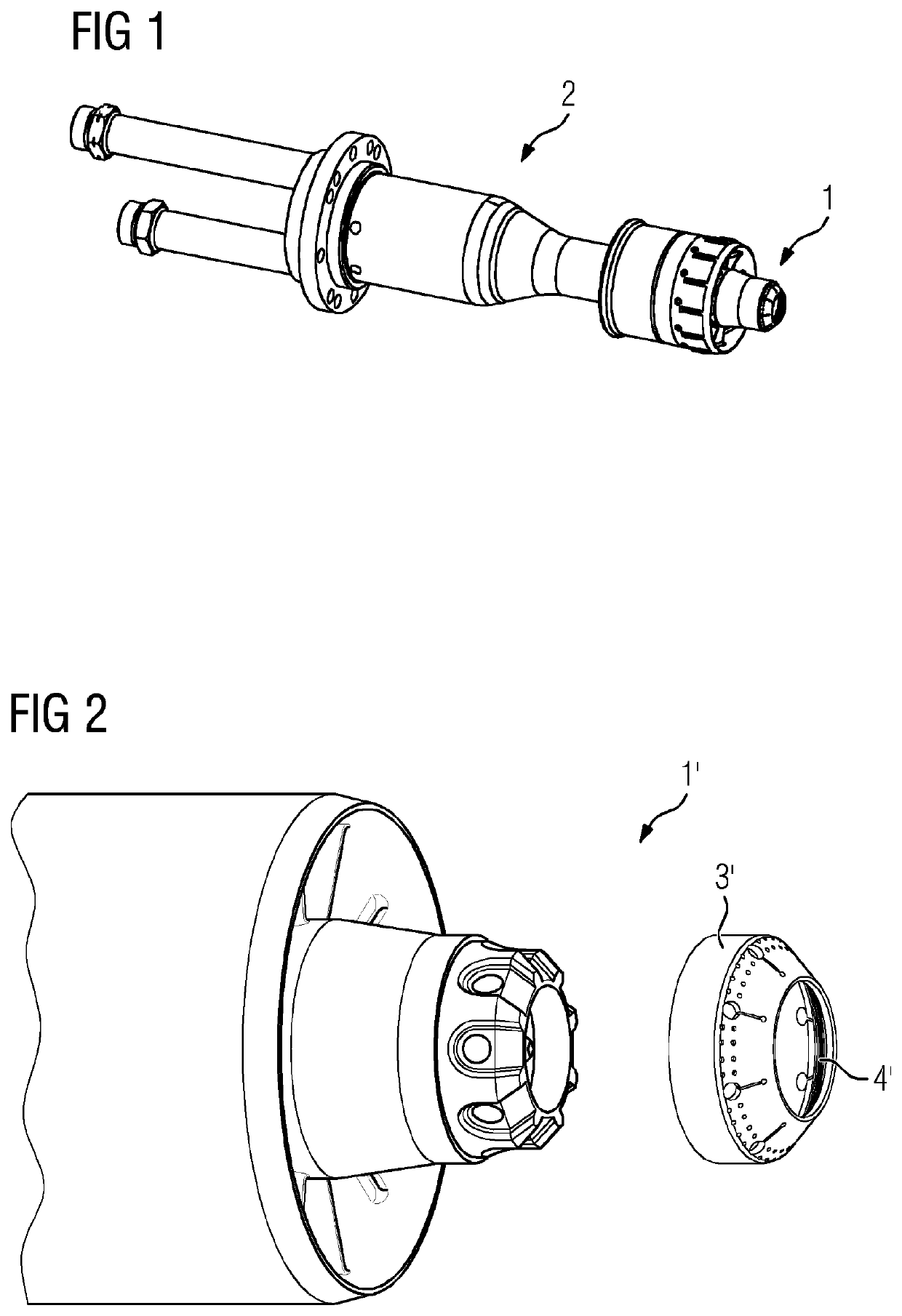
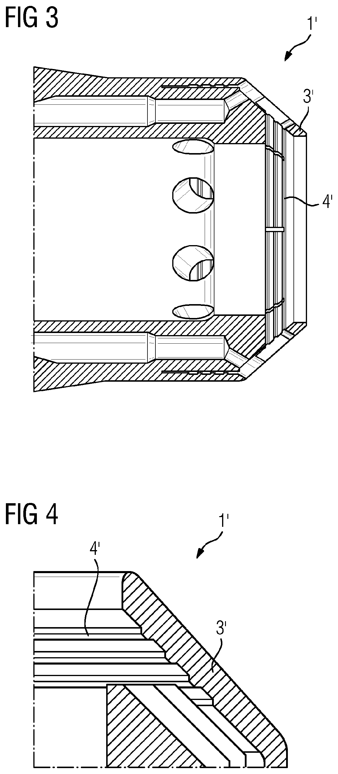
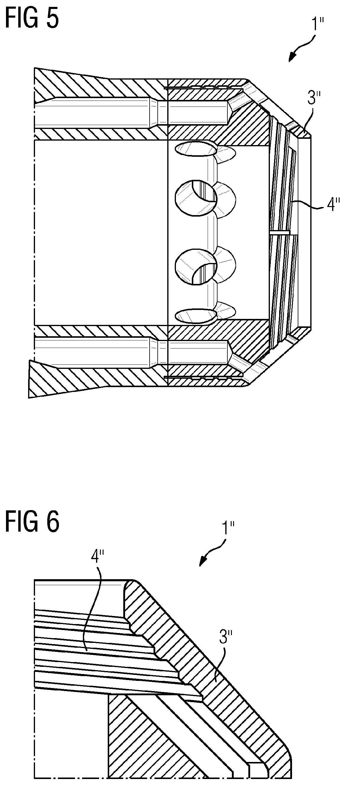
This patent describes a new burner for a gas turbine engine that improves the life of the burner tip and reduces stress on the engine. The burner tip has cooling fins that provide better heat exchange and can be easily attached to the end of the burner or separately manufactured. This makes it easier to replace damaged tips and upgrade the engine with the improved burners. The use of the inventive burners allows for improved engine performance with low effort.

Problems solved by technology

However, building up the burner tip directly upon the remaining part of the burner is a difficult task.

Method used


Image

  • Burner for use in a streaming engine
  • Burner for use in a streaming engine
  • Burner for use in a streaming engine

Examples


Embodiment Construction

[0018]According to one aspect the present invention refers to a burner as specified above.

[0019]The helical arrangement of the at least one cooling fin results in a multitude of cooling fins provided in a cross-section along the flow direction of the combustion channel. It was noted that it is advantageous that such arrangements are provided in every cross-section along the flow direction of the combustion channel. According to further embodiments it is advantageous that the burner tip provides at least 2, more advantageous at least 3, even more advantageous at least 4, cooling fins in a cross-section along the flow direction of the combustion channel.

[0020]In further embodiments it is advantageous that the at least one cooling fin of the burner provides at least 2, more advantageous at least 3, more advantageous at least 5, cooling fins being essentially parallel, more advantageous parallel, to each other within the burner tip. The term “essentially parallel to each other” as used ...


PUM


Abstract

A burner adapted for use in a streaming engine, wherein the burner provides a combustion channel and a burner tip, wherein the burner tip provides at least one longitudinal cooling fin, and wherein the at least one longitudinal cooling fin provides a longitudinal direction helically circling the combustion channel.

Description

CROSS REFERENCE TO RELATED APPLICATIONS[0001]This application is the US National Stage of International Application No. PCT / EP2020 / 060146 filed 9 Apr. 2020, and claims the benefit thereof. The International Application claims the benefit of European Application No. EP19178465 filed 5 Jun. 2019. All of the applications are incorporated by reference herein in their entirety.FIELD OF INVENTION[0002]The present invention refers to an optimized burner to be used in the streaming engine. Furthermore, the present invention refers to a burner tip providing an improved design. Additionally, the present invention refers to the method of manufacturing such burner and / or burner tip. Furthermore, the present invention refers to a streaming engine providing such improved burner. Additionally, the present invention refers to the use of such improved burner.BACKGROUND OF INVENTION[0003]Burners are essential components of streaming engines like gas turbines. Herein, they play an essential role to pr...

Claims


Application Information

Patent Timeline
Patent Type & Authority Applications(United States)
IPC IPC(8): F23R3/28F02C7/12
CPCF23R3/283F02C7/12F23R2900/00004F23D2900/00016
Inventor ERIKSSON, JONASJOKISCH, TORSTENKLEINFELD, JENS
Owner SIEMENS ENERGY GLOBAL GMBH & CO KG
Learn More