Automated nozzle adjustments for plant treatment application

a technology of automatic adjustment and nozzle adjustment, which is applied in the field of system for applying treatment fluid, can solve the problems of large manual burden, wear and tear of nozzles, and human error, and achieve the effect of reducing the number of manual adjustments

Pending Publication Date: 2022-08-11
BLUE RIVER TECH
View PDF0 Cites 0 Cited by
  • Summary
  • Abstract
  • Description
  • Claims
  • Application Information

AI Technical Summary

Benefits of technology

[0004]A farming machine is configured to move through a field and treat one or more plants in the field using various treatment mechanisms. A treatment mechanism may include a plurality of nozzle holders with each nozzle holder of the plurality of nozzle holders including a plurality of nozzles. Each nozzle is configured to couple to a valve and to dispense treatment fluid. The valve is configured to regulate the dispensing of treatment fluid. One or more nozzle holders may be automatically adjusted (e.g., the positioning of one or more nozzle holders may be adjusted) based on plant treatment instructions. In some embodiments, the plant treatment instructions include a treatment position for a nozzle holder. The treatment mechanism determines a current position of the nozzle holder and adjusts the position of the nozzle holder from the current position to the treatment position. In some embodiments, the treatment mechanism may determine one or more nozzles of the plurality of nozzles are unable to dispense treatment fluid (e.g., are blocked, clogged, or worn out). Based on this determination, the treatment mechanism may adjust the position of one or more nozzle holders such that operable nozzles are coupled to the valve.
[0005]In some embodiments, a farming machine is described for treating one or more plants in a field. The farming machine comprises a treatment mechanism configured to dispense treatment fluid to one or more plants as the farming machine travels past the plants in a field. The treatment mechanism comprises a valve for regulating the dispensing of treatment fluid, a nozzle holder comprising a plurality of nozzles, and a control system. Each nozzle is configured to dispense treatment fluid and to couple to the valve. The control system is configured to receive a plant treatment instruction for treating the plants. The plant treatment instruction comprises a treatment position for a nozzle holder. The treatment position for a nozzle holder is a position of the nozzle holder which enables the farming machine to provide the treatment corresponding to the treatment instruction. That is, in the treatment position the nozzle holder couples a nozzle that will apply the desired treatment to the valve. Additionally, each nozzle in a nozzle holder corresponds to a position of the nozzle holder that couples it to the valve. Each position may be a treatment position when the treatment instruction is for its corresponding nozzle.
[0006]The control system is further configured to determine a current position of the nozzle holder in the treatment mechanism. The control system determines the current position of the nozzle holder by receiving a magnetic field measurement produced by one or more magnets positioned in the nozzle holder and identifying the current position of the nozzle holder based on the measurement of the magnetic field. The control system is further configured to automatically adjust the current position of the nozzle holder to the treatment position for the nozzle holder. The control system is further configured to actuate, based on the plant treatment instruction, the treatment mechanism such that the plants are treated via a nozzle while the nozzle holder is in the treatment position as the farming machine moves past the plants in the field.

Problems solved by technology

Over time nozzles wear-out and need to be replaced.
Typically, swapping and / or replacing the nozzles is a large manual burden and can suffer from human error.

Method used


Image

  • Automated nozzle adjustments for plant treatment application
  • Automated nozzle adjustments for plant treatment application
  • Automated nozzle adjustments for plant treatment application

Examples


Embodiment Construction

I. Farming Machine

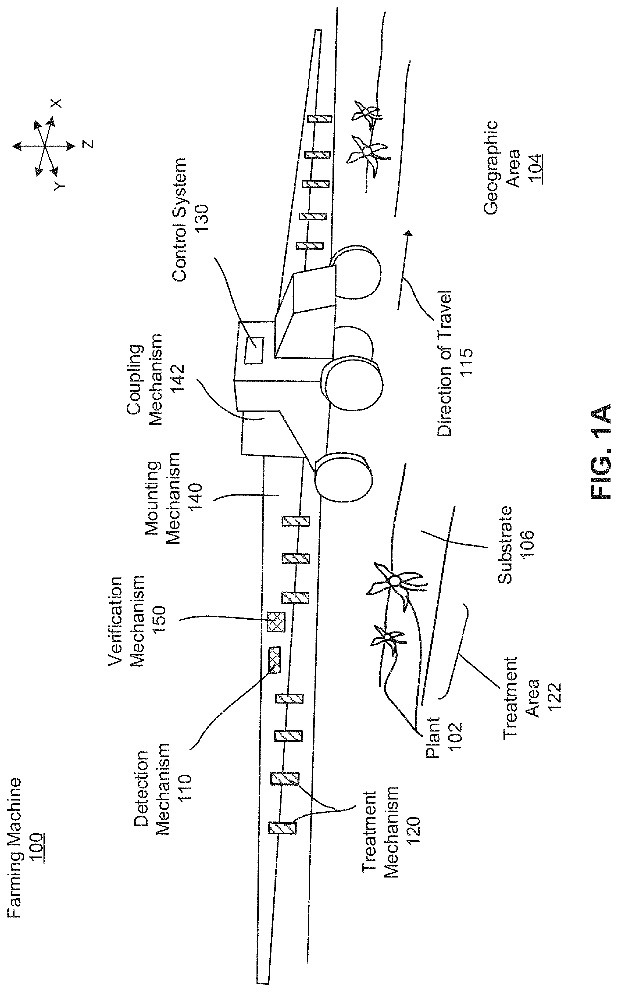
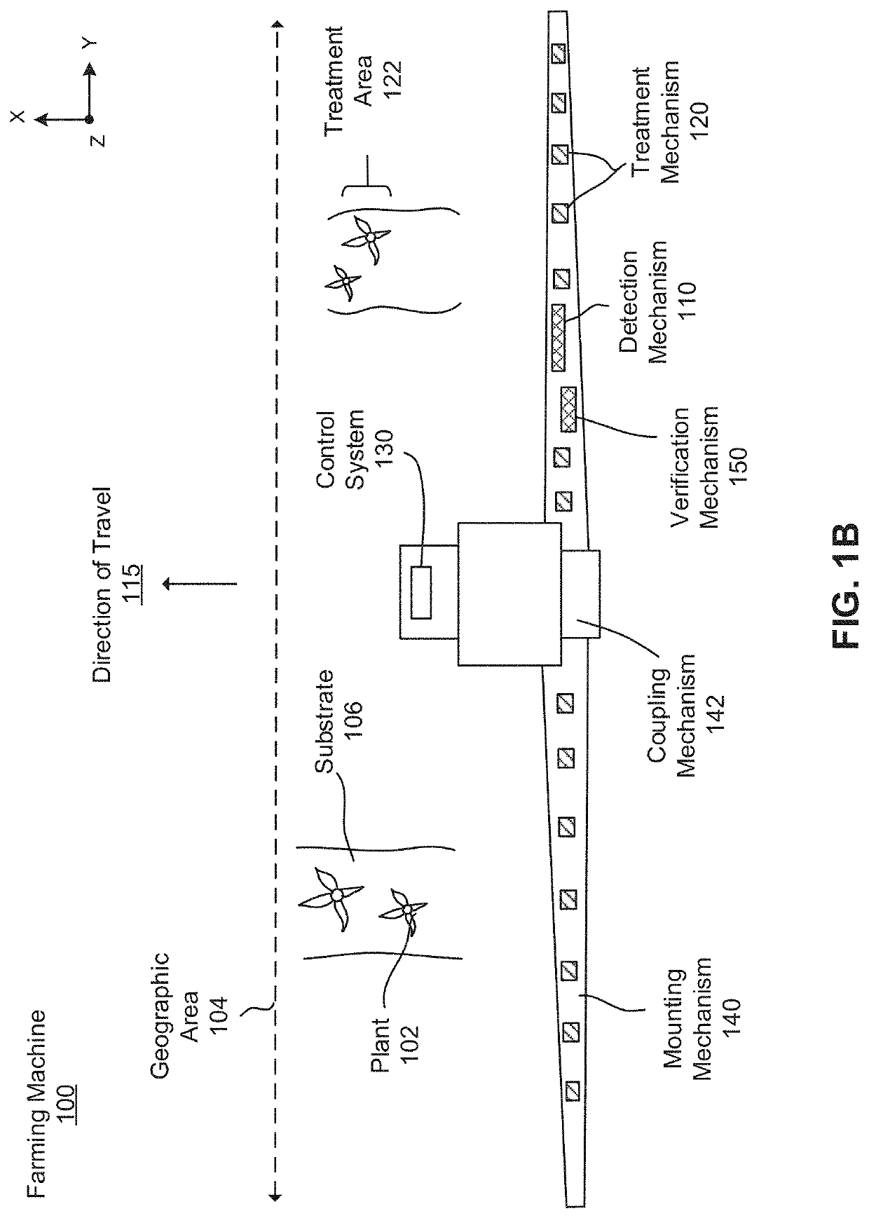
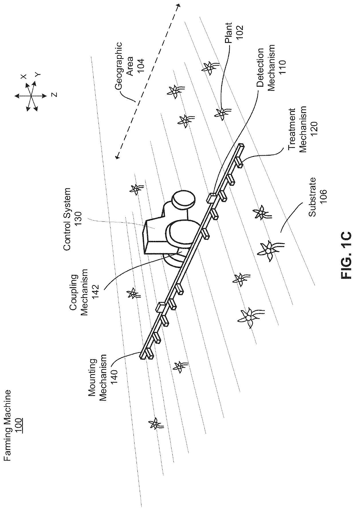
[0022]A farming machine that identifies and treats plants may have a variety of configurations, some of which are described in greater detail below. For example, FIG. 1A is an isometric view of a farming machine and FIG. 1B is a top view of the farming machine of FIG. 1A. FIG. 1C is a second embodiment of a farming machine. Other embodiments of a farming machine are also possible. The farming machine 100, illustrated in FIGS. 1A-1C, includes a detection mechanism 110, a treatment mechanism 120, and a control system 130. The farming machine 100 can additionally include a mounting mechanism 140, a verification mechanism 150, a power source, digital memory, communication apparatus, or any other suitable component. The farming machine 100 can include additional or fewer components than described herein. Furthermore, the components of the farming machine 100 can have different or additional functions than described below.

[0023]The farming machine 100 functions to apply ...


PUM


Abstract

A treatment mechanism for dispensing treatment fluid onto one or more plants in a field is described. The treatment mechanism includes a valve for regulating the dispensing of treatment fluid and a nozzle holder comprising a plurality of nozzles. Each nozzle is configured to dispense treatment fluid and to couple to the valve. The treatment mechanism further includes a control system configured to receive a plant treatment instruction for treating the plants. The plant treatment instruction includes a treatment position for the nozzle holder. The control system is further configured to determine a current position of the nozzle holder and adjust the current position of the nozzle holder to the treatment position for the nozzle holder. The control system is further configured to actuate the treatment mechanism such that the plants are treated via a nozzle of the plurality of nozzles.

Description

CROSS-REFERENCE TO RELATED APPLICATION[0001]This application claims the benefit of priority to U.S. Provisional Patent Application No. 63 / 146,433, filed on Feb. 5, 2021, which is incorporated by reference in its entirety.BACKGROUNDField of Disclosure[0002]This disclosure relates to a system for applying treatment fluid to plants in a field, and more specifically to automatically adjusting nozzles for dispensing treatment fluid.Description of the Related Art[0003]Current methods for spraying plant treatment (e.g., herbicide treatment, fungicide treatment, etc.) on plants in a field utilize high-density spray nozzles. Each spray nozzle in the spray system is uniform. Over time nozzles wear-out and need to be replaced. Additionally, nozzles must be replaced for different types of application of plant treatment (e.g., broadcast application, spot spraying, etc.). Typically, swapping and / or replacing the nozzles is a large manual burden and can suffer from human error.SUMMARY[0004]A farmi...

Claims


Application Information

Patent Timeline
Patent Type & Authority Applications(United States)
IPC IPC(8): A01M7/00A01C23/04
CPCA01M7/006A01C23/047A01M7/0089
Inventor ANDERSON, KENT MICHAELCHOSTNER, BENJAMIN RAYMAJUSIAK, BRYON WILLIAM
Owner BLUE RIVER TECH
Why Eureka
Try Eureka