Method for reinforcing a panel and a method for manufacturing a composite panel implementing such a method

a technology of reinforcing a panel and a manufacturing method, which is applied in the field of reinforcing a panel and manufacturing a composite panel, to achieve the effects of minimizing internal tension, reducing surface density, and minimizing internal stresses

Pending Publication Date: 2022-08-11
SOC INT POUR LE COMMERCE & LIND +1
View PDF0 Cites 0 Cited by
  • Summary
  • Abstract
  • Description
  • Claims
  • Application Information

AI Technical Summary

Benefits of technology

[0048]Guaranteeing a bore with a controlled cylindrical geometry, minimizing internal tensions, then allows to insert the reinforcing element, which is in particular fibrous, according to step d) with a controlled lining, in particular a controlled section of the reinforcing element, but without excess so as not to lose the cylindrical geometry giving the final shape of the reinforcement bridges during the application of the resin.
[0180]The reinforcement method is notable and advantageous in that it allows to obtain reinforcing bridges between skins, with reinforcing fiber content greater than 30%, or even 40% by volume, in particular between 40% and 89%, by volume or even between 45% and 89% by volume, or even between 40% and 80%, or even between 45% and 75%, or even between 45% and 70% by volume, namely a significant amount of fibers compared to the polymerized resin of the reinforcing bridges.
[0184]to ensure the creation of a bore with a controlled rectilinear trajectory, minimizing internal stresses, even if the panel material is a multilayer, including different superimposed layers of different materials and of different densities, or else if the panel comprises facing sheets, for example metallic sheets, and even if the drilling angle is not, locally at the drilling point, perpendicular to the surface of the panel to be pierced, or else locally perpendicular to the intermediate surfaces of the different layers of the panel.
[0189]a reinforcing fiber content in the reinforcing bridges comprised between 30% and 80% by volume, in particular between 45% and 70%.
[0190]In particular, said panel (excluding the skin) may be a multilayer of different densities and / or of different materials and / or having metal facing sheets Par1, Par2.
[0191]Advantageously, the possibility of providing reinforcing bridges with a consequent diameter, for example greater than 3 mm, or even 5 mm, 7 mm, 8 mm or even 9 mm allows to reduce the surface density of the number of reinforcing bridges, but also to provide such reinforcements in panels of significant thickness.

Problems solved by technology

The main drawback of stitching reinforcement techniques is their very long implementation due to the work of the needle, and unlike the needling reinforcement techniques which are at a higher rate.
Conversely, the main drawback in needling techniques is their random nature in the sense that it cannot be guaranteed that the barbs of the needles actually pull the fibers: in such a case a quantified presence of the fibrous reinforcements in the panel cannot be guaranteed, and unlike the techniques of reinforcement by stitching.
In both cases, these techniques have the additional drawback of not allowing any distribution of the fibrous reinforcements in the core material, or even any inclination of the reinforcements, and due to the techniques and stitching (or needling) equipment used to insert these fibrous reinforcements into the panel of the core material.
In other words, such a method does not allow to ensure a sufficient amount of fibers in the reinforcing bridges.
According to the findings of the inventors, such a method according to US2008 / 0226876A1 ensuring the insertion of a reinforcing element by pulling its longitudinal end, is unreliable, in particular if there is significant friction between the reinforcing element and the panel in the bore during insertion.
According to the findings of the inventors, such a method does not allow the reliable, automated and industrial insertion of a textile reinforcement, while minimizing the clearance between the perforated bore and the textile reinforcing element.
According to the tests carried out by the inventors, the use of a needle as a piercing tool generates problems the intensity of the disadvantages of which increases with the increase in the section (or diameter) of the needle used and in particular:a risk of tearing of the cellular material which increases according to the section of the needle, due to the work of the needle and the stresses applied by the needle to the material, in particular when the needle emerges from the cellular material,the hole formed by the needle being obtained by piercing and deforming the cellular material (without removing material), this piercing locally modifies the density of the cellular material at the holes, with a compression of the material in the vicinity of the hole compared to the cellular material located further from a hole, compression which may moreover not be constant depending on the thickness of the cellular material, and again,the local compression of the core material according to its thickness gives rise to internal tensions which do not allow to guarantee a cylindrical hole geometry according to the thickness.
According to the tests carried out by the inventors, once this hole has been made by the work of the needle, the final geometry of the hole is still impacted by the traction of the loop of fibers within the hole, which gives rise to ovalization phenomena depending on the thickness in particular for polyurethane foams, namely after impregnation of the resin within the reinforcement, the geometry of the reinforcement cannot be guaranteed.
According to the findings of the inventors, such a method according to US.3030.256 B1, WO2006 / 125562 and EP 3.173.216 A1, requires reinforcing the panel with fibrous reinforcements of small section, in order to minimize the disadvantages, and therefore to provide a surface density of the reinforcements (number of fibrous reinforcements relative to the surface of the panel) of high number, which has the disadvantage of increasing the manufacturing time, and therefore the cost of the reinforced product.

Method used


Image

  • Method for reinforcing a panel and a method for manufacturing a composite panel implementing such a method
  • Method for reinforcing a panel and a method for manufacturing a composite panel implementing such a method
  • Method for reinforcing a panel and a method for manufacturing a composite panel implementing such a method

Examples


examples

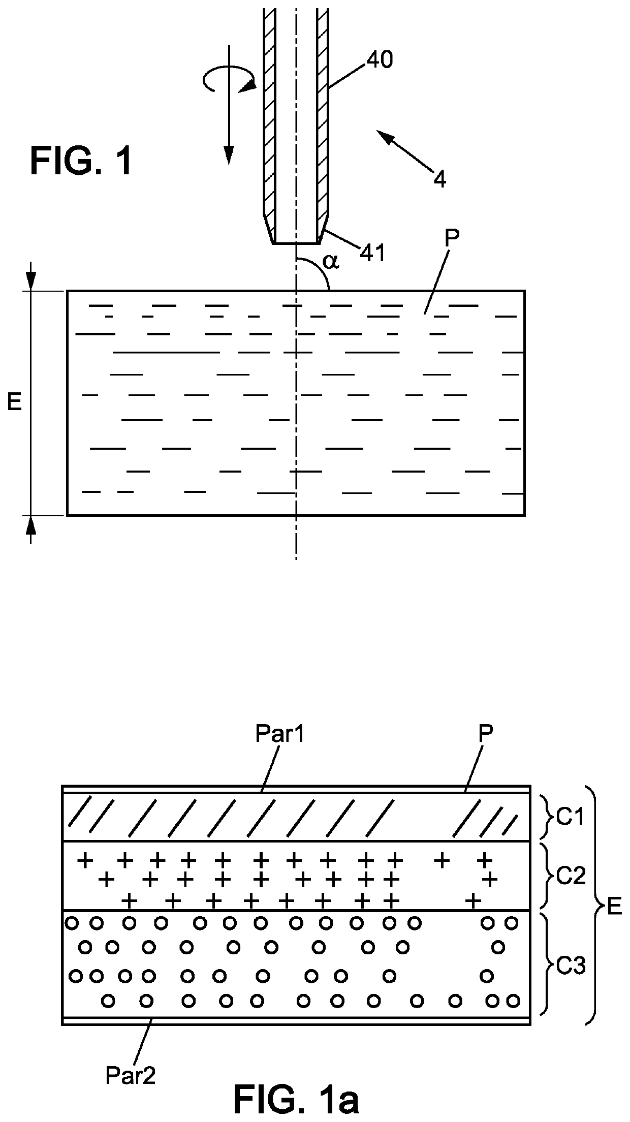
[0192]Three examples of composite panels are detailed below with three different materials for the panel.

[0193]These three examples, however, have the following common features:[0194]They are obtained by the vacuum infusion molding technique, with a vacuum of the order of 0.9 bar below atmospheric pressure and the use of an epoxy resin,[0195]The two skins are made of a 0 / 90° bidirectional woven roving glass sheet,[0196]the core material—the panel—is in a closed cell foam of thickness E equal to 50 mm,[0197]the yarns of the reinforcing elements are made of glass fibers, each thread has a count of 300 Tex.

[0198]Example 1 Acrylic core material (PMI) reinforced by the method presented according to different coring diameters and the bores of which were lined according to different filling rates.

TABLE 2ReinforcementReinforcementbridge no1bridge no2ØNbFiberFiberDiameterFiber contentExtLineofØcontentØcontentAvgStandardAvgStandardAvg(mm)Noyarns(mm)(% m)(mm)(% m)(mm)deviation(% m)deviation(% ...


PUM

PropertyMeasurementUnit
internal diameteraaaaaaaaaa

Abstract

A method for reinforcing a panel according to its thickness, including: a step a) of providing a reinforcing element which is elongated, flexible, with two longitudinal ends having a length strictly greater than twice the thickness of the panel; a step b) of positioning and holding the reinforcing element on one side of the panel, called the insertion side; a step c) of gripping the reinforcing element, in its middle, on the insertion side, an insertion step d) wherein the reinforcing element gripped by its middle is pulled through a bore passing through the panel, by folding the reinforcing element back on itself, and to a final position, wherein the two longitudinal ends project or not from the bore on the insertion side, a loop of the reinforcing element projecting or not from the bore on the side of the panel opposite to the insertion side.

Description

[0001]The invention relates to a method for reinforcing a panel according to its thickness, as well as a method for manufacturing composite panels using such a panel reinforcement method.TECHNICAL FIELD[0002]The present disclosure relates to the field of the manufacture of composite sandwiches, also called composite panels. A composite sandwich substantially comprises three elements which are superimposed, flat, or 3D preformed, depending on its thickness, namely two skins and an interlayer core material, conventionally in the shape of a panel which is flat or 3D preformed, intimately bonded to the two skins. In the context of the present disclosure, the core material reinforced by the insertion of one (or more) reinforcing element(s) can be, by way of non-limiting example, a panel of cellular foam such as polyethylene foams (PE), polyethylene terephthalate (PET) foams, polyurethane (PUR) foams, acrylic foams (PMI), bio-sourced foams, and also various materials such as cork for exam...

Claims


Application Information

Patent Timeline
Patent Type & Authority Applications(United States)
IPC IPC(8): B29C70/24B29C70/08
CPCB29C70/24B29C70/086B29C70/443B29C70/545B29C70/68B65F1/16B29C2793/0045B29C2793/0027
Inventor MARCOVICH, PHILIPPESAJET, PHILIPPECOUVREUR, XAVIERLESTOQUOY, CHARLESLAINE, CYRIL
Owner SOC INT POUR LE COMMERCE & LIND
Why Eureka
Try Eureka