
Wall Structure with Horizontal Base Stud

a technology of horizontal base and wall structure, which is applied in the direction of girders, walls, joists, etc., can solve the problems of significant damage, time-consuming and costly remaining clean up, and potential growth of mildew in the area

Active Publication Date: 2022-08-11
COX MICHAEL ELLIOTT
View PDF11 Cites 0 Cited by
  • Summary
  • Abstract
  • Description
  • Claims
  • Application Information

AI Technical Summary

Benefits of technology

The invention offers a quick and easy way to dry walls after plumbing leaks, water intrusion, or floods. This method avoids the need for mold and mildew remediation, as there is no water damage to the wall panels. All that is required is the removal of the coping piece or baseboard, drying of the area, and replacing the coping piece or baseboard.

Problems solved by technology

Because the drywall is installed with a lower edge adjacent the floor of the room, any water intrusion from flooding, or a leak from plumbing systems, such as showers, toilets, sinks, etc., can cause significant damage from splashing, soaking, water wicking, where mold and mildew can potentially grow in the areas that are damaged.
Once the water is removed from the floor, the remaining clean up is time consuming and costly.
The water will have soaked into the wall material, and if left untreated, mold and mildew will grow creating contamination and health issues.
This results in significant business disruption and loss of revenue.
As is evident, the entire process involves several steps and time, requiring the services of outside contractors, carpenters, painters, and housekeeping personnel, all the while making the room unusable.
The length of time the room is not being used for patient care is time consuming and costly.

Method used


Image

  • Wall Structure with Horizontal Base Stud
  • Wall Structure with Horizontal Base Stud
  • Wall Structure with Horizontal Base Stud

Examples


Embodiment Construction

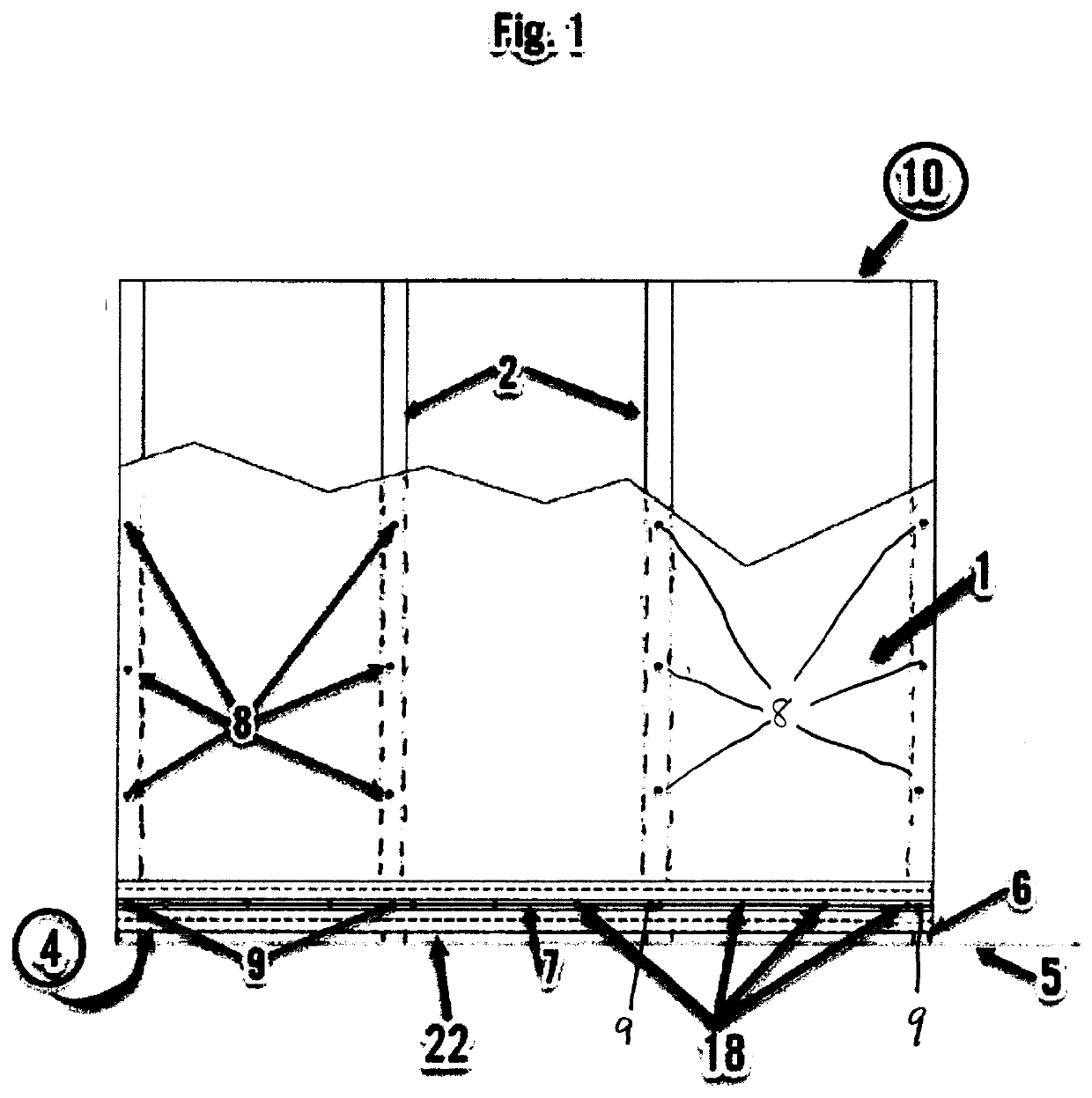
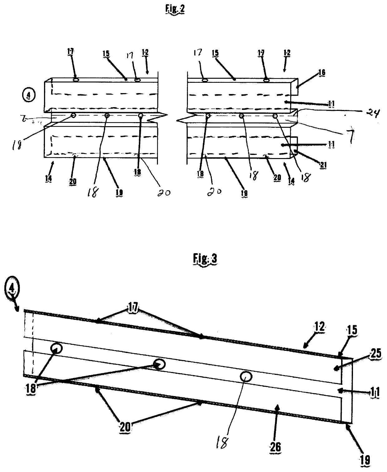
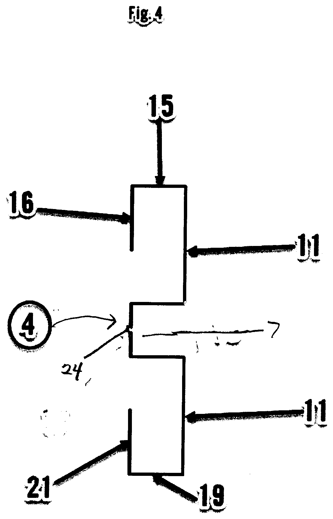
[0025]A wall structure 10 of a preferred embodiment of this invention is shown in FIG. 1. A wall panel 1 is shown secured to vertical studs 2 via screws 8, above horizontal base stud 4. Base stud 4 is shown spaced 22 apart and above floor 5. Wall panel 1 can be made of conventional panel materials known in the art, such as drywall, solid wood, faux wood, particle board, laminate, metal, plastic, and the like, and can be in any thickness. Preferably, the material is drywall, and is ½ or ⅝ inch thick. Wall panel 1 is secured to vertical studs 2 by conventional means, such as via adhesive, and / or screws 8. Vertical studs 2 are made of materials known in the art, and in an industrial setting, are preferably metal, such as steel or aluminum. Wall panel 1 is secured above horizontal base stud 4. The horizontal base stud 4 is secured to vertical studs 2 through an indented central portion 7 via typical means, and preferably via screws 9. The thickness of the indent is the same as thickness...


PUM


Abstract

A wall structure having a horizontal base stud, which wall structure has an upper wall panel, and a horizontal base stud, wherein the base stud has openings to allow for liquids to escape in the event of a plumbing leak, and additional openings to allow for air flow from the exterior to the interior of the wall structure.

Description

CROSS-REFERENCE TO RELATED APPLICATIONS[0001]This application claims the benefit of U.S. Provisional Application No. 63 / 146,668, filed Feb. 7, 2021; and U.S. Provisional Application No. 63 / 238,841, filed Aug. 31, 2021, the disclosures of which are hereby expressly incorporated by reference herein in their entirety.FIELD OF THE INVENTION[0002]This invention relates to the creation of a new category of wall construction that employs horizontal studs at the base of the wall, and above the floor. It can be used in new construction, renovation, and remodeling. When installed at the bottom of a wall, this horizontal base stud system addresses the problem of how to keep drywall dry during a plumbing leak, water intrusion, or flood, by raising the drywall up off of the floor.[0003]In new construction, the horizontal base stud will be installed first near ground level, then the drywall can be installed immediately above the horizontal base stud. In renovation or remodeling applications, the ...

Claims


Application Information

Patent Timeline
Patent Type & Authority Applications(United States)
IPC IPC(8): E04B1/00E04B2/58E04B2/70
CPCE04B1/0023E04B2/70E04B2/58E04B2/7457E04B2/7854E04B1/70E04C3/07E04B2/60E04C2003/0443E04F19/049E04F19/0481E04B1/7038E04F19/04E04F2019/0445E04F19/0495
Inventor COX, MICHAEL ELLIOTT
Owner COX MICHAEL ELLIOTT
Learn More