
Light-emitting element and ranging apparatus

a technology of light-emitting elements and ranging apparatus, which is applied in the direction of instruments, semiconductor lasers, and using reradiation, etc., can solve the problem that the ranging method is not suitable for long-distance measuremen

Pending Publication Date: 2022-08-18
SONY SEMICON SOLUTIONS CORP
View PDF0 Cites 1 Cited by
  • Summary
  • Abstract
  • Description
  • Claims
  • Application Information

AI Technical Summary

Benefits of technology

The patent text is saying that when multiple light emitters are used, the one in the center may not have the highest efficiency of extracting light compared to those in the surrounding areas.

Problems solved by technology

However, this ranging method is not suitable for a long-distance measurement.

Method used


Image

  • Light-emitting element and ranging apparatus
  • Light-emitting element and ranging apparatus
  • Light-emitting element and ranging apparatus

Examples


Embodiment Construction

[0093]A ranging apparatus according to embodiments of the present technology is described.

[0094][Configuration of Ranging Apparatus]

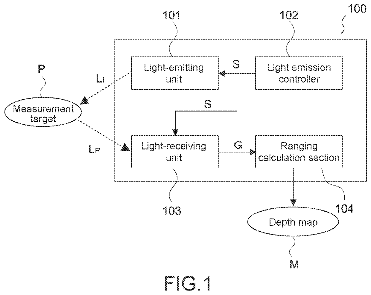
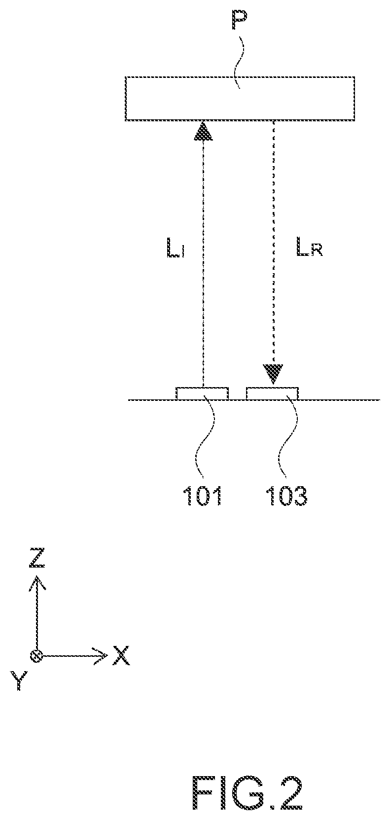
[0095]FIG. 1 is a block diagram illustrating a configuration of a ranging apparatus 100 according to the present embodiment. As illustrated in the figure, the ranging apparatus 100 includes a light-emitting unit 101, a light emission controller 102, a light-receiving unit 103, and a ranging calculation section 104.

[0096]The light-emitting unit 101 irradiates a measurement target P with irradiation light LI of which the brightness is periodically changed. When a light-emission control signal S is supplied by the light emission controller 102, the light-emitting unit 101 generates the irradiation light LI in synchronization with the light-emission control signal S. The configuration of the light-emitting unit 101 will be described later.

[0097]The light emission controller 102 controls a light emission of the light-emitting unit 101. The light emission con...


PUM

PropertyMeasurementUnit
frequencyaaaaaaaaaa
diameter D1aaaaaaaaaa

Abstract

[Object] To provide a light-emitting element that has a vertical-cavity surface-emitting laser structure and is suitable for a long-distance light irradiation, and a ranging apparatus.[Solving Means] A light-emitting element according to the present technology includes a plurality of light emitters, a first electrode terminal, and a second electrode terminal. The plurality of light emitters is a plurality of light emitters one-dimensionally or two-dimensionally arranged in a direction that is vertical to an optical axis corresponding to light that exits each of the plurality of light emitters, each of the plurality of light emitters being a vertical-cavity surface-emitting laser element, each of the plurality of light emitters including a first electrode and a second electrode, each of the plurality of light emitters emitting the light due to current flowing from the first electrode to the second electrode. The first electrode terminal is electrically connected to the first electrode. The second electrode terminal is electrically connected to the second electrode. A current path from the first electrode terminal to the second electrode terminal that passes through one of the plurality of light emitters exhibits an electrical resistance different from an electrical resistance of a current path from the first electrode terminal to the second electrode terminal that passes through another of the plurality of light emitters.

Description

TECHNICAL FIELD[0001]The present technology relates to a light-emitting element that has a vertical-cavity surface-emitting laser structure, and a ranging apparatus.BACKGROUND ART[0002]A time-of-flight (ToF) method is a ranging method. In the TOF method, light is emitted by a light emitter, and the light reflected off a measurement-target object is detected by a detector. This makes it possible to measure a three-dimensional shape of the measurement-target object.[0003]For example, a ranging method is known that includes diffusing, by a diffusion plate, pieces of light that respectively exit a plurality of light emitters, irradiating the diffused pieces of light onto a measurement-target range, and detecting the reflected pieces of light by a light detector that includes two dimensionally arranged light-receiving / emitting sections. In this ranging method, exiting light is diffused by a diffusion plate. Thus, a short-distance measurement can be performed over a range of light. Howeve...

Claims


Application Information

Patent Timeline
Patent Type & Authority Applications(United States)
IPC IPC(8): G01S7/481H01S5/42H01S5/042G01S17/08
CPCG01S7/4815G01S17/08H01S5/04256H01S5/423H01S5/183H01S5/18361G01S7/484H01S5/0428H01S5/02345H01S5/18311H01S5/18394H01S5/18344H01S5/18391H01S2301/20H01S2301/18H01S5/18327H01S5/40
Inventor KOBAYASHI, TAKASHIWAKABAYASHI, KAZUYAKIMURA, MOTOIOIWA, TATSUYA
Owner SONY SEMICON SOLUTIONS CORP
Learn More