
Electrical shunt apparatus and system

a technology of electric shunts and shunts, which is applied in the direction of electric vehicles, vehicle components, transportation and packaging, etc., can solve the problems of temporary interruption of the electrical connection between the wheel and the running surface, and the insufficient connectivity of the wheel and axle shun

Pending Publication Date: 2022-08-25
GE GLOBAL SOURCING LLC
View PDF0 Cites 0 Cited by
  • Summary
  • Abstract
  • Description
  • Claims
  • Application Information

AI Technical Summary

Benefits of technology

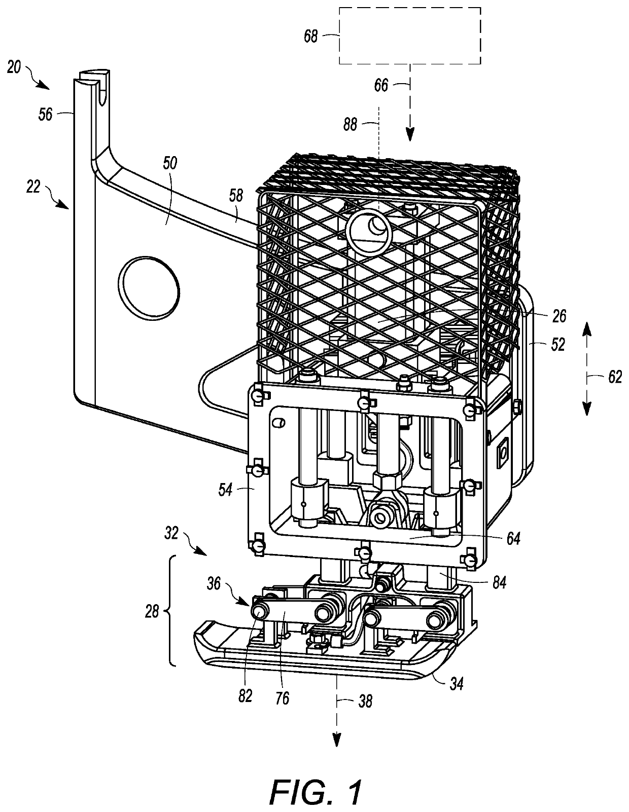
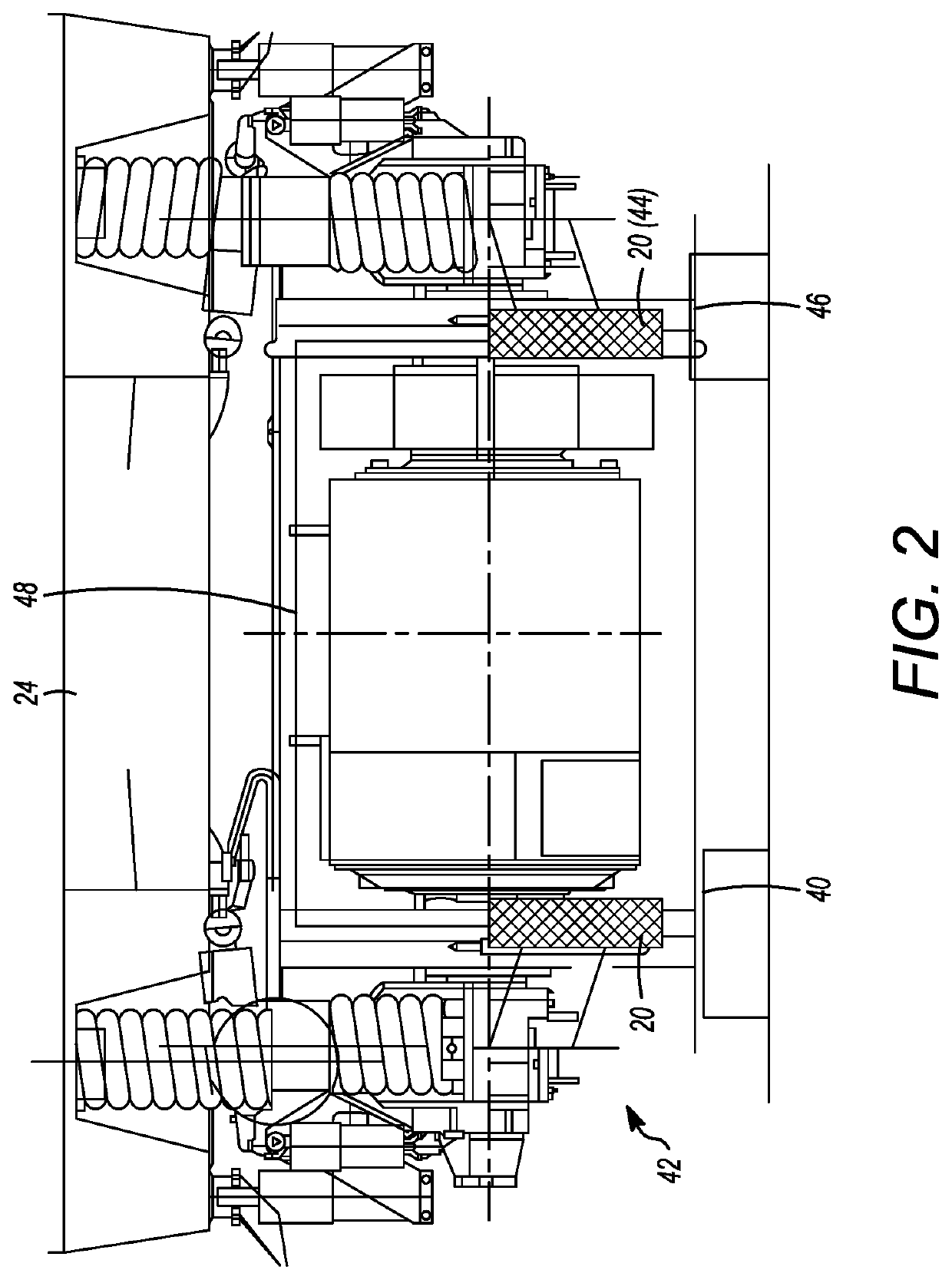
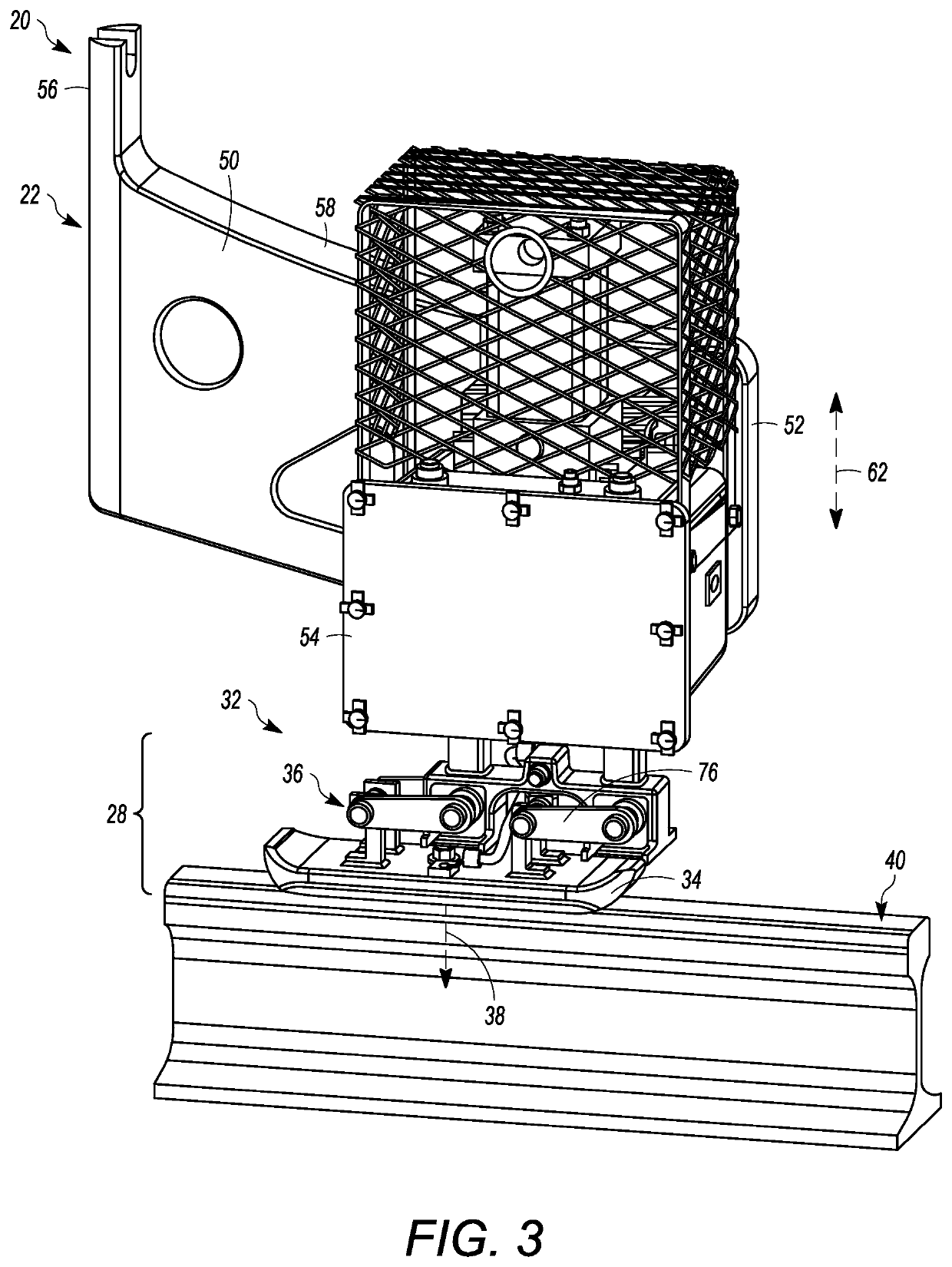
The patent is about a device called a shunt apparatus that is used to shunt electrical current from a vehicle's rail system to the vehicle's electrical system. The apparatus includes a mounting bracket that attaches to the vehicle, an actuator that moves a shoe unit, and a resilient biasing assembly that presses the shoe against the running surface when the vehicle moves. The patent describes a system where two of these apparatuses are attached to the vehicle's sides and their shoes are connected by an electrical conductor. This allows for electrical shunting when the shoes touch the running surfaces. The technical effect of this invention is that it provides a more reliable and consistent path for electrical current to flow through the vehicle's rail system.

Problems solved by technology

However, due to the complex operational environment in which such vehicles operate, wheel-and-axle shunts may not provide enough connectivity (timewise, and / or in terms of signal strength) for certain vehicle control applications.
For example, substances like water or ice on the running surface may cause temporary interruptions in the electrical connection between a wheel and running surface.

Method used


Image

  • Electrical shunt apparatus and system
  • Electrical shunt apparatus and system
  • Electrical shunt apparatus and system

Examples


Embodiment Construction

[0015]Embodiments of the subject matter described herein relate to electrical shunt systems for vehicles, e.g., for electrically shunting conductive running surfaces on or along which a vehicle operates, for vehicle location determination or other signaling purposes. In one aspect, a shunt apparatus may include a mounting bracket assembly configured for connection to a vehicle, an actuator connected to the mounting bracket assembly, and a shoe unit connected to the actuator. The actuator is controllable to move the shoe unit from a retracted position to an extended position. The shoe unit includes a conductive shoe, and a biasing assembly that is configured to exert a force on the shoe, e.g., in the direction of the extended position. When the apparatus is operably deployed onboard a vehicle and the actuator is controlled to move the shoe unit to the extended position, the conductive shoe is positioned to contact a conductive first running surface on which the vehicle travels. Concu...


PUM


Abstract

A shunt apparatus includes a mounting bracket assembly configured for connection to a vehicle, an actuator connected to the mounting bracket assembly, and a shoe unit connected to the actuator. The actuator is controllable to move the shoe unit to an extended position where a conductive shoe of the shoe unit is positioned to contact a conductive first running surface on which the vehicle travels. The shoe unit includes a resilient biasing assembly that is configured to exert a force on the shoe, to press the shoe against the running surface during movement of the vehicle. Two of the shunt apparatuses may be attached to opposite sides of the vehicle. The shoes of the two shunt apparatuses are electrically connected to one another by an electrical cable. When the shoes are brought into contact with respective running surfaces, the running surfaces are electrically shunted for vehicle signaling purposes or otherwise.

Description

CROSS-REFERENCE TO RELATED APPLICATIONS[0001]This application claims priority to U.S. Provisional Application No. 63 / 151,498 (filed 19 Feb. 2021), the entire disclosure of which is incorporated by reference herein.BACKGROUNDTechnical Field[0002]Embodiments of the subject matter herein relate to electrical shunts. Other embodiments relate to electrical shunts for vehicles.Discussion of Art[0003]Some vehicle control systems utilize shunt connections onboard a vehicle for electrically interconnecting or shorting two adjacent, conductive running surfaces on which the vehicle operates, e.g., two sections of parallel rail track. The running surfaces are shunted for establishing an electrical connection therebetween, e.g., for purposes of determining a location of the vehicle along a route of the running surfaces using signaling techniques. The shunt connection is established by the conductive (e.g., metal) traction components of the vehicle, namely, an electrical connection that extends f...

Claims


Application Information

Patent Timeline
Patent Type & Authority Applications(United States)
IPC IPC(8): B60L5/38
CPCB60L5/38H01R11/11
Inventor MCMAHAN, TRAVISKNOX, II, STEVEN J.PIOTROWSKI, GARYSMITH, STACY NEIL
Owner GE GLOBAL SOURCING LLC
Learn More