
Brake of an Idler Roll of a Fiber Web Machine, in particular of a Slitter-winder

a technology of fiber web machine and idler roll, which is applied in the direction of calenders, thin material processing, papermaking, etc., can solve the problems of significant work safety risks, loss of production time, and easy wear of contact surfaces

Pending Publication Date: 2022-08-25
VALMET TECH OY
View PDF0 Cites 0 Cited by
  • Summary
  • Abstract
  • Description
  • Claims
  • Application Information

AI Technical Summary

Benefits of technology

The patent describes a brake used on a fiber web machine that prevents the idler roll from rotating freely. This increases the capacity of the section and reduces braking time to one tenth compared to no brake. The brake is compact, secure, and cost-effective, with a frame that protects the operator from contacting the moving parts of the brake.

Problems solved by technology

This causes losses in production time as it is necessary to wait until the idler roll stops before the slitter-winder or other section or device of a fiber web machine can be restarted.
Additionally, in some cases in connection of the web breaks broke is caused and it is necessary to manually clean out the broke.
In this situation, freely rotating, even with rotating speeds of several thousand rounds per minute, idler rolls cause significant work safety risks.
In these kinds of stopping devices i.e., brakes, which contact the surface of the roll to be stopped, one disadvantage is that the contacting surfaces are susceptible to wear.
Thus, the brakes need maintenance and changes at regular intervals.
With these kinds of brakes, which effect the braking based on electromagnetism, a disadvantage is that the construction is complicated and thus, it is not very cost effective, especially bearing in mind that even one slitter-winder may comprise several idler rolls and especially several segmented rolls, each needing several brakes as a brake is needed for each segment of roll.

Method used


Image

  • Brake of an Idler Roll of a Fiber Web Machine, in particular of a Slitter-winder
  • Brake of an Idler Roll of a Fiber Web Machine, in particular of a Slitter-winder

Examples


Embodiment Construction

[0043]During the course of this description like numbers and signs will be used to identify like elements according to the different views which illustrate the invention. Repetition of some reference signs may have been omitted in the figures for clarity reasons.

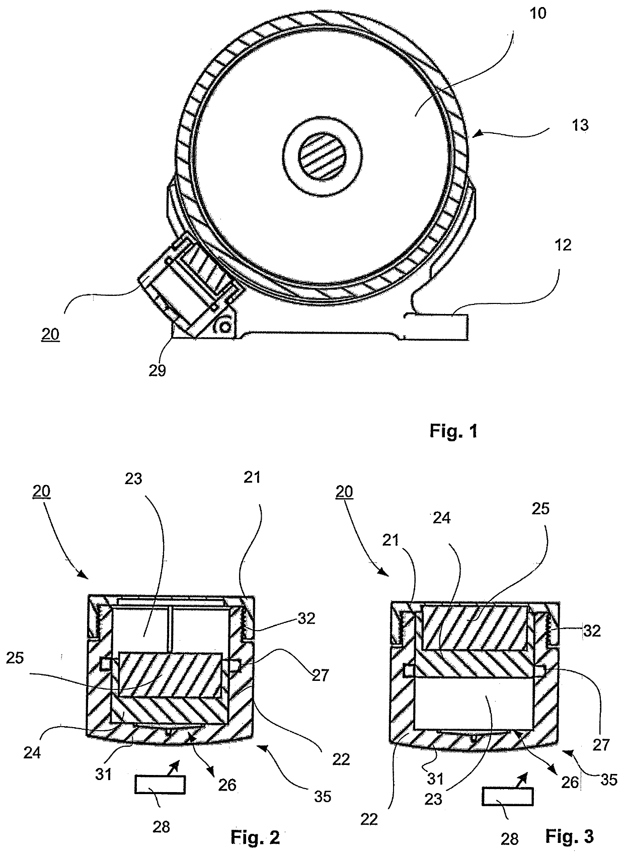
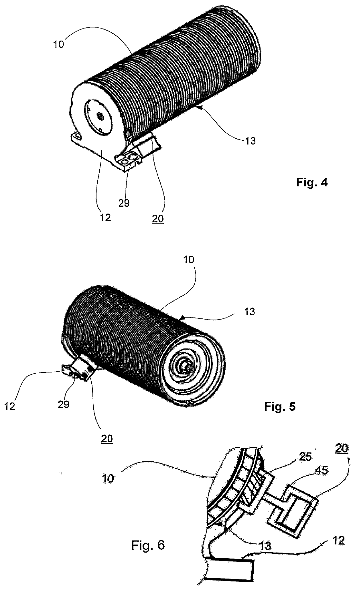
[0044]In FIGS. 1 and 4-6 is shown an idler roll 10 with a brake 20. The idler roll 10 comprises an outer shell surface 13 and a mounting frame 12, to which the brake 20 is attached by a fastener 29 such that the brake 20 is located outside the outer shell surface 13 of the idler roll 10 in close vicinity of the idler roll 10 in a non-contacting position i.e., the brake 20 is not in contact with the outer shell surface 13 of the idler roll 10. The brake 20 comprises a permanent magnet 25, which is movable from a non-braking position to a braking position and vice versa, by an actuator, which in the example of FIGS. 2-5 is a piston 35 and in the example of FIG. 6 a permanent magnet is connected by a rod 45 to a piston in a cyl...


PUM

PropertyMeasurementUnit
Lengthaaaaaaaaaa
Lengthaaaaaaaaaa
Diameteraaaaaaaaaa

Abstract

A brake is provided for an idler roll (10) of a fiber web machine, in particular of a slitter-winder, which idler roll (10) has an outer shell surface (13). The brake (20) is located outside the outer shell surface (13) of the idler roll (10) in close vicinity of the idler roll (10) in a non-contacting position. The brake (20) has a permanent magnet (25), which is configured to be moved from non-braking position to a braking position and vice versa by an actuator or cylinder (35, 45).

Description

CROSS REFERENCES TO RELATED APPLICATIONS[0001]This application claims priority on Finnish Application No. 20215138, filed Feb. 11, 2021, the disclosure of which is incorporated by reference herein.STATEMENT AS TO RIGHTS TO INVENTIONS MADE UNDER FEDERALLY SPONSORED RESEARCH AND DEVELOPMENT[0002]Not applicable.BACKGROUND OF THE INVENTION[0003]The invention relates in general to slitter-winders for winding longitudinally slit paper and board webs into customer rolls and to braking idler rolls. Especially the invention relates to a brake for an idler roll of a slitter winder.[0004]It is known that a fiber web, e.g., paper, is manufactured in machines which together constitute a paper-manufacturing line which can be hundreds of meters long. Modern paper machines can produce over 450,000 tons of paper per year. The speed of the paper machine can exceed 2,000 m / min and the width of the paper web can be more than 11 meters.[0005]In paper-manufacturing lines, the manufacture of paper takes p...

Claims


Application Information

Patent Timeline
IPC IPC(8): B65H27/00D21G1/02
CPCB65H27/00D21G1/02B65H2301/4148B65H2403/7254B65H2555/13F16D49/00F16D65/16B65H35/02B65H23/038B65H2701/1133F16D2121/04B65H18/08B65H26/025B65H2403/7253B65H2404/167B65H2404/1321B65H2801/84F16D63/002
Inventor LESKINEN, ARTO
Owner VALMET TECH OY
Learn More