
Hydrostatic displacement unit

Inactive Publication Date: 2009-06-18
SAUER DANFOSS NORDBERG
View PDF5 Cites 2 Cited by
  • Summary
  • Abstract
  • Description
  • Claims
  • Application Information

AI Technical Summary

Benefits of technology

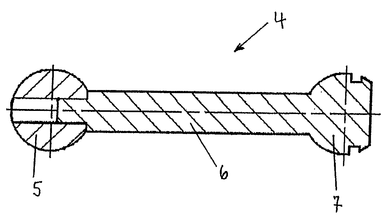
[0005]In an alternative embodiment, the pistons are formed as composite pistons. In this way, it is possible to select the optimum material combinations for those parts of the piston which are particularly susceptible to wear, specifically the piston head and piston base in combination with the cylinder or piston base materials.
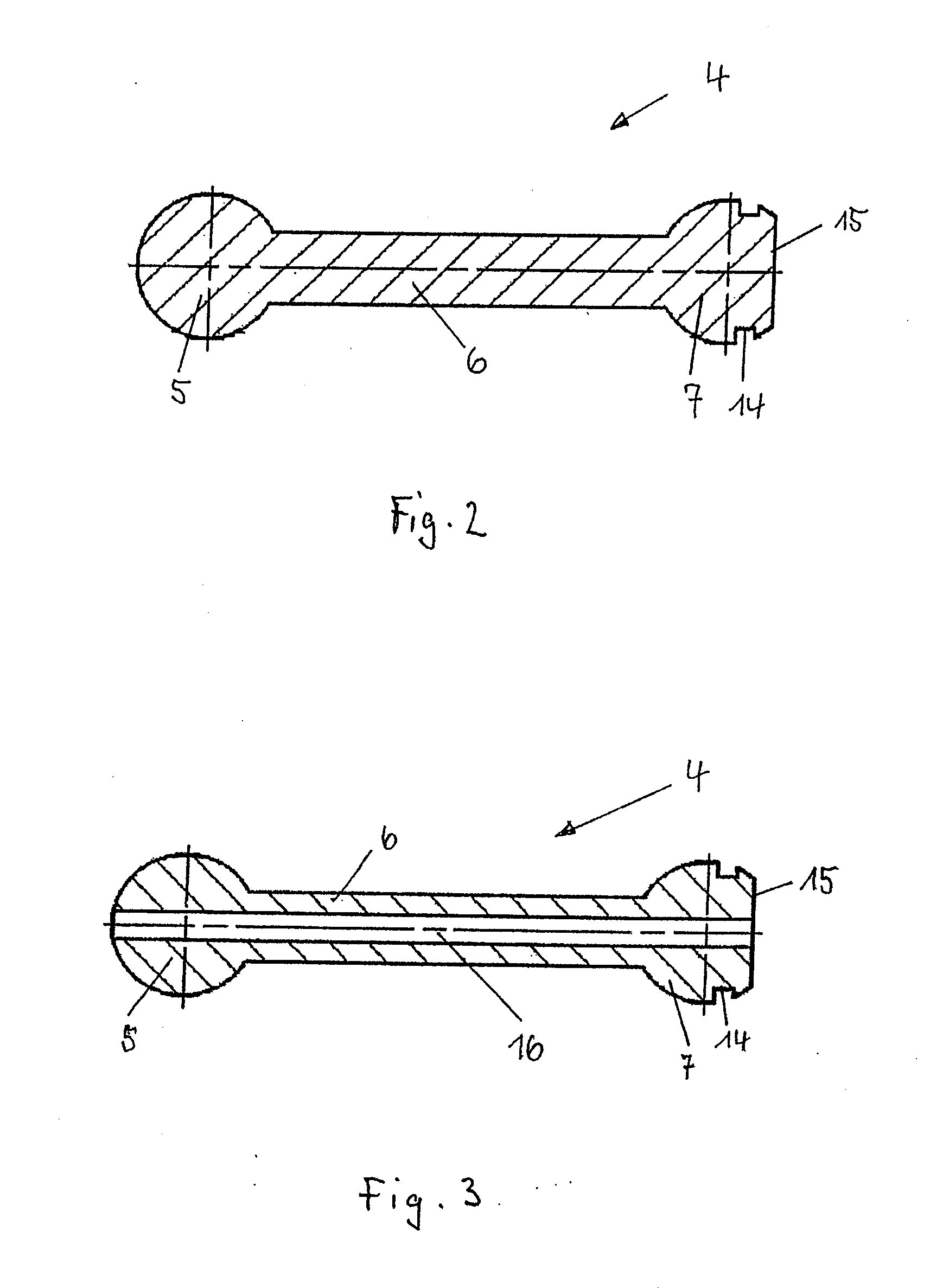
[0006]The piston is preferably formed as a hollow piston, as a result of which it is possible to obtain a further reduction in the piston mass. It is also advantageous if the piston has a longitudinal bore, in such a way that the pressure medium can pass in a metered quantity to the piston base and can serve here as lubricant in the region of the support of the piston. Here, the piston base is preferably of spherical design and is held by a corresponding ball socket of a sliding shoe or piston base or directly in the flange of the driveshaft.
[0007]It is also advantageous if the piston head is of convex or spherical design. In this way, the piston does not need to be guided linearly through a relatively long cylindrical part, but rather can perform a pivoting movement about the longitudinal axis of the cylinder within a certain angle. This is advantageous in particular in oblique-axle power units in which the pistons are supported on the drive flange of the shaft at an adjustable angle, as a result of which the piston shank travels through a certain angle range about the cylinder longitudinal axis during the reciprocating movement of the piston. The sealing of the cylinder space is provided here by one or more piston rings. Said piston rings are held by grooves which are formed in an encircling manner in the piston head.

Problems solved by technology

The rotational speed limit of displacement units is limited inter alia by the wear between the piston and cylinder block.
This firstly means a considerable level of production expenditure and entails not inconsiderable costs.
Secondly, pistons composed of steel therefore still have a relatively large mass moment of inertia which leads to said susceptibility to wear and to a limitation of the rotational speeds which can be obtained.

Method used


Image

  • Hydrostatic displacement unit
  • Hydrostatic displacement unit
  • Hydrostatic displacement unit

Examples


Embodiment Construction

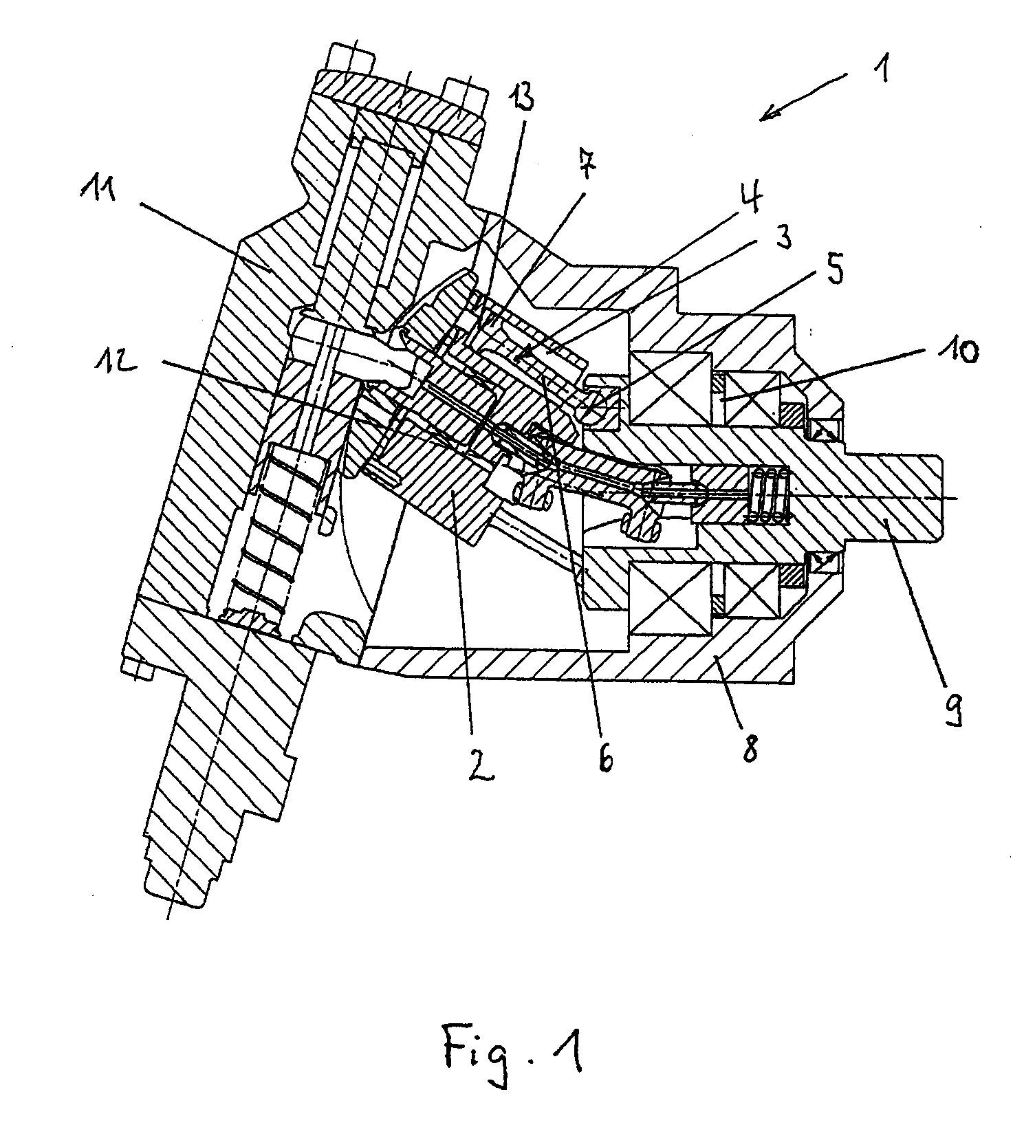
[0016]FIG. 1 shows a displacement unit 1 according to the invention as an example of a hydraulic motor embodied as an oblique-axle power unit. The unit can in principle also be operated as a pump. The displacement unit 1 has a cylinder block 2 which is mounted so as to be rotatable about its longitudinal central axis and has cylinder bores 3 distributed about its periphery, in which cylinder bores 3 pistons 4 are movable. The cylinder block 2 is mounted in the housing 8 so as to be pivotable about a pivot axis which runs transversely with respect to its rotational axis, so that the longitudinal central axis of the cylinder block 2 forms an adjustable angle with the axis of the driveshaft 9 which itself is fixedly mounted in a bearing 10 in the housing 8. Here, the pistons 4 are articulatedly supported with the piston base 5 on a support device, in this case the flange of the driveshaft 9, at the set angle. The adjustment takes place by means of an adjusting device 11, by means of wh...


PUM


Abstract

A hydrostatic displacement unit having pistons which are composed at least partially of a high-grade aluminum material which are made of one piece or a composite to reduce wear.

Description

BACKGROUND OF THE INVENTION[0001]The invention relates to a hydrostatic displacement unit as per the preamble of claim 1 and relates to displacement units which have a driveshaft and a cylinder block which has cylinder bores in which pistons are mounted in a longitudinally movable manner. The pistons are composed of a piston head, a piston shank and a piston base, the piston base being supported on a support device in such a way that, with rotation of the driveshaft, the piston head is movable in a reciprocating fashion in its cylinder. Displacement units of said type can be embodied as a pump or a hydraulic motor which can, for example, be used in traction drives as a continuously variable hydrostatic transmission.[0002]The rotational speed limit of displacement units is limited inter alia by the wear between the piston and cylinder block. Here, a particularly critical component is the pistons whose design greatly influences the performance and service life of the displacement unit...

Claims


Application Information

Patent Timeline
IPC IPC(8): F16J1/08F16J1/01F16H39/04
CPCF04B1/124F05C2201/021F04B1/328
Inventor REIMER, MARKUSHEIN, MICHAEL
Owner SAUER DANFOSS NORDBERG
Learn More