
Flame simulating device and atomizing simulation fireplace including same

Pending Publication Date: 2022-08-25
NINGBO RICHEN ELECTRIC APPLIANCE CO LTD
View PDF8 Cites 0 Cited by
  • Summary
  • Abstract
  • Description
  • Claims
  • Application Information

AI Technical Summary

Problems solved by technology

To enhance the three-dimensional effect, some flame simulating devices add a simulated fuel bed with light, but the simulated fuel bed is usually only self-illuminating and cannot form the shape of leaping flames, so it is not realistic.
However, the flame simulating device currently on the market usually needs not only to introduce a disturbing air flow inside the mist generating chamber to cause mist or water vapor to flow out from the atomizer, but also to provide a guiding air flow for guiding the mist to flow upward after the mist or water vapor emerges from the atom

Method used


Image

  • Flame simulating device and atomizing simulation fireplace including same
  • Flame simulating device and atomizing simulation fireplace including same
  • Flame simulating device and atomizing simulation fireplace including same

Examples


Example

Embodiment 1

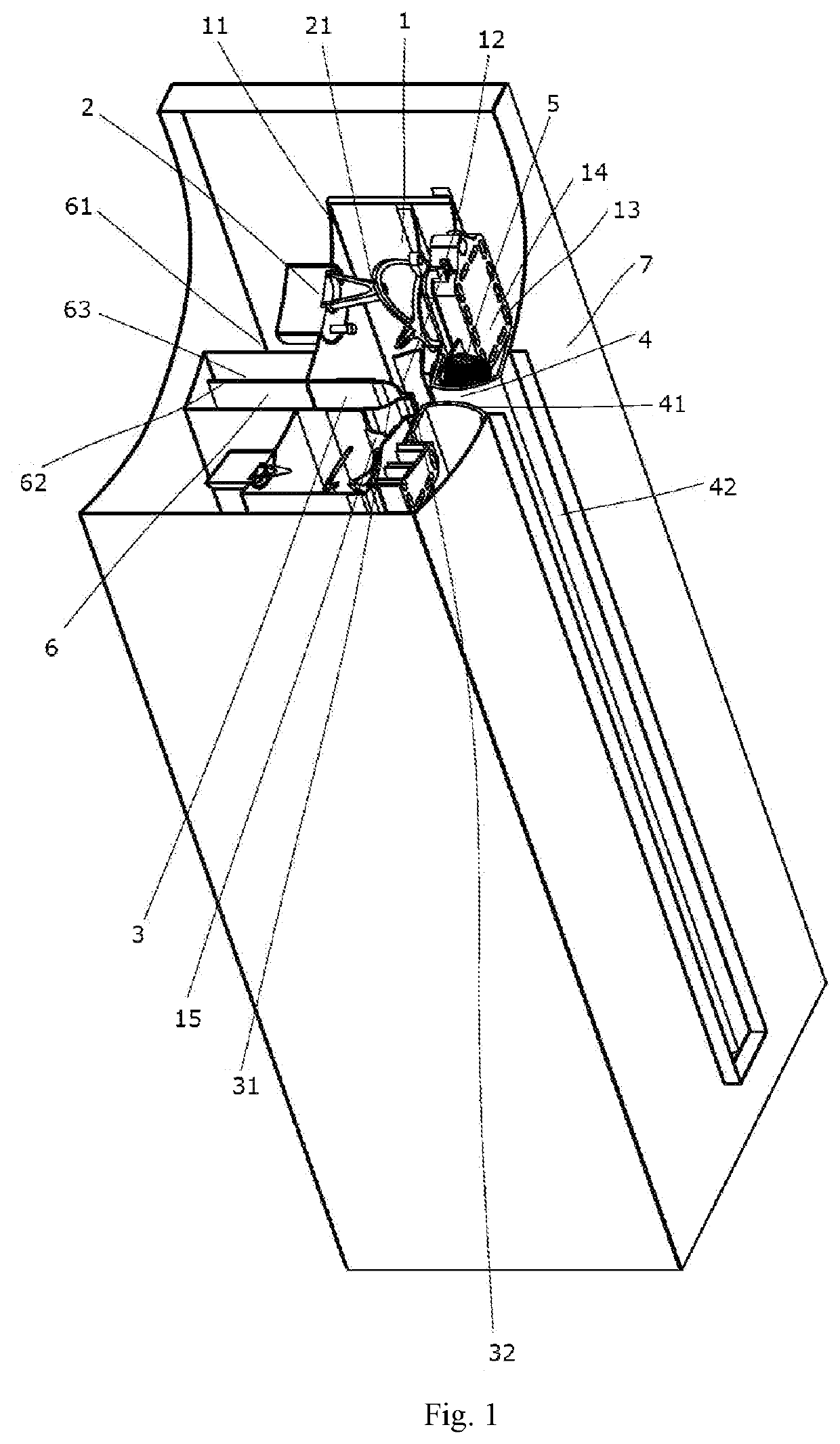
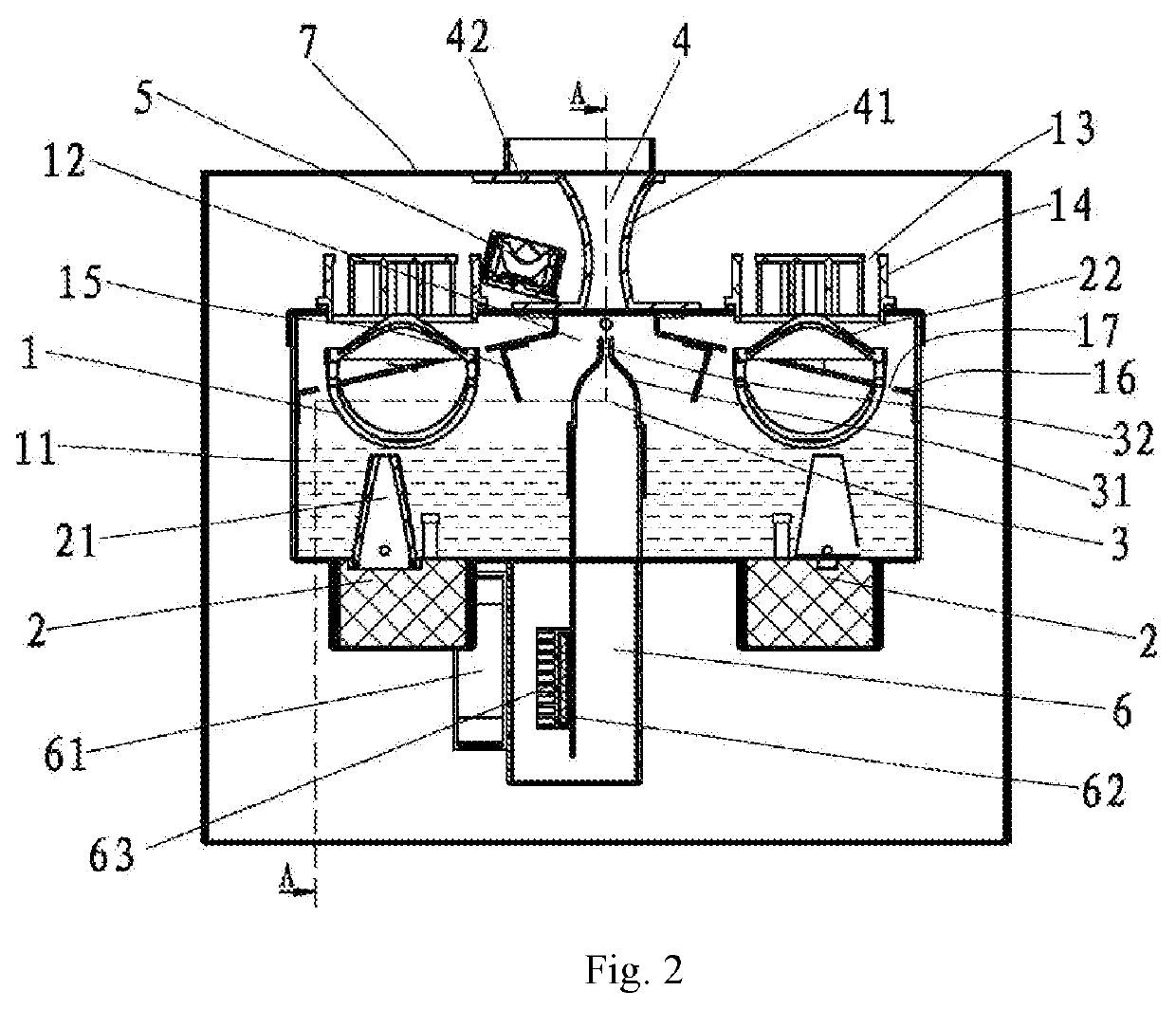
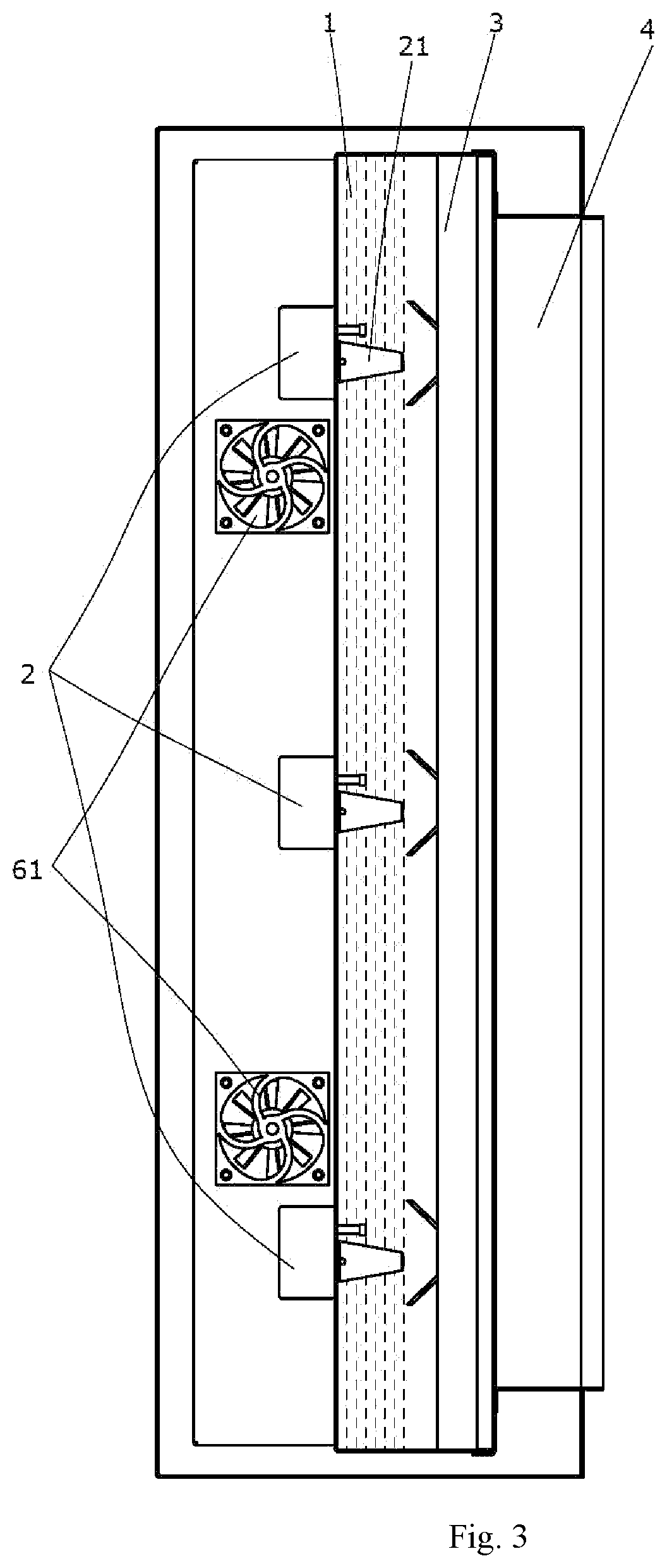
[0061]As shown in FIG. 1 to FIG. 8, a flame simulating device includes a mist generating chamber 1, an atomizing head 2, an air orifice 3 and a nozzle 4. The flame simulating device further includes a light source 5 and a transparent cover 42. The nozzle 4 is elongated in the longitudinal direction and is defined by nozzle walls 41 with Coanda curved surface shapes on both sides. The Coanda surface in this embodiment is an arc-shaped curved surface. The minimum dimension B of the nozzle walls 41 on both sides of the cross section of the nozzle 4 is preferably 2 mm to 20 mm, and the dimension shown in this embodiment is about 5 mm. The air orifice 3 is disposed below the nozzle 4. In this embodiment, the dimension of the air orifice 4 in the longitudinal direction is slightly longer than the length dimension of the nozzle 4, and the air orifice 3 is defined by air orifice walls 31 on both sides. The cross-sectional shape of the air orifice 3 is a flared, triangular or tra...

Example

Embodiment 2

[0064]A flame simulating device is shown in FIG. 9 to FIG. 10. In Embodiment 2, compared with Embodiment 1, the mist generating chamber 1 is arranged on a single side with respect to the air orifice 3 and the nozzle 4, only one nozzle wall 41 is a Coanda curved surface, and the light source 5 is arranged on the other side with respect to the mist generating chamber 1.

[0065]The mist generating chamber 1 is disposed only on one side of the air orifice 3, thereby saving the space, facilitating mounting and increasing the volume of the liquid storage tank 8.

Example

Embodiment 3

[0066]As shown in FIG. 11 to FIG. 19, an atomizing simulation fireplace includes a mist generating chamber 1, an atomizing head 2, an air orifice 3, a nozzle 4, a light source 5, an outer casing 7 and a simulated fuel bed 9. The nozzle 4 is elongated in the longitudinal direction and is defined by nozzle walls 41 with Coanda curved surface shapes on both sides. The Coanda surface in this embodiment is an arc-shaped curved surface. The minimum dimension B of the nozzle walls 41 on both sides of the cross section of the nozzle 4 is preferably 2 mm to 20 mm, and the dimension shown in this embodiment is about 5 mm. The air orifice 3 is disposed below the nozzle 4. In this embodiment, the dimension of the air orifice 4 in the longitudinal direction is slightly longer than the length dimension of the nozzle 4, and the air orifice 3 is defined by air orifice walls 31 on both sides. The cross-sectional shape of the air orifice 3 is a flared shape with a gentle and smooth transi...


PUM


Abstract

The present invention discloses a flame simulating device, comprising a mist generating chamber, an atomizing head, an air orifice and a nozzle. The inside of the mist generating chamber is provided with a liquid and the atomizing head, the atomizing head being capable of atomizing the liquid inside the mist generating chamber, the two sides of the nozzle being set as Coanda curved surfaces, the cross section of the air orifice being in a constricted shape and providing an air flow blown upward such that under the Venturi effect, the air flow blown upward will guide and attract the mist from inside the mist generating chamber to vent out and flow into a nozzle inlet; the upper surface of the mist generating chamber is provided with a breathing port, and the breathing port directly faces the atomizing head. Due to the Coanda curved surface on the side of the nozzle, the mist flows along both sides of the nozzle under the Coanda effect and then vents out of the nozzle.

Description

CROSS REFERENCE TO RELATED APPLICATIONS[0001]The present application is a Continuation-in Part of U.S. application Ser. No. 16 / 585,354 filed Sep. 27, 2019, which claims priority to China Application No. 201910470468.X filed on May 31, 2019 and China Application No. 201920812881.5 filed May 31, 2019, the subject matter of each of which are incorporated herein by reference in their entirety.TECHNICAL FIELD[0002]The present invention belongs to the technical field of atomizing electric fireplaces and relates to a flame simulating device for forming a flame shape by an atomizing device and an atomizing simulation fireplace including the same.BACKGROUND ART[0003]At present, most of the electric fireplace flame simulating devices on the market use a light source to irradiate the moving parts, and then the reflective elements on the moving parts are used for reflective projection imaging, for example, the simulation flame simulating device that is mentioned in CN 200920118478.9. This kind ...

Claims


Application Information

Patent Timeline
IPC IPC(8): F21S10/04F24B1/18F21S10/00F24D13/00
CPCF21S10/04F24B1/1808F21S10/002F24D13/00F24C7/004B05B7/0087
Inventor ZHOU, YIN
Owner NINGBO RICHEN ELECTRIC APPLIANCE CO LTD
Learn More