Inductor component

Pending Publication Date: 2022-08-25
MURATA MFG CO LTD
View PDF0 Cites 0 Cited by
  • Summary
  • Abstract
  • Description
  • Claims
  • Application Information

AI Technical Summary

Problems solved by technology

It has been found out that the small thickness of the coil wiring at the highest level may lower reliability of connection between the coil wiring at the highest level and the other outer electrode.
If the thickness of the emulsio

Method used


Image

  • Inductor component
  • Inductor component
  • Inductor component

Examples


first embodiment

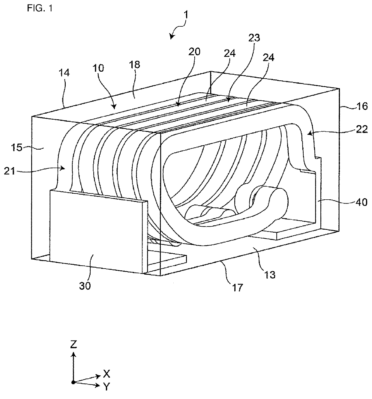
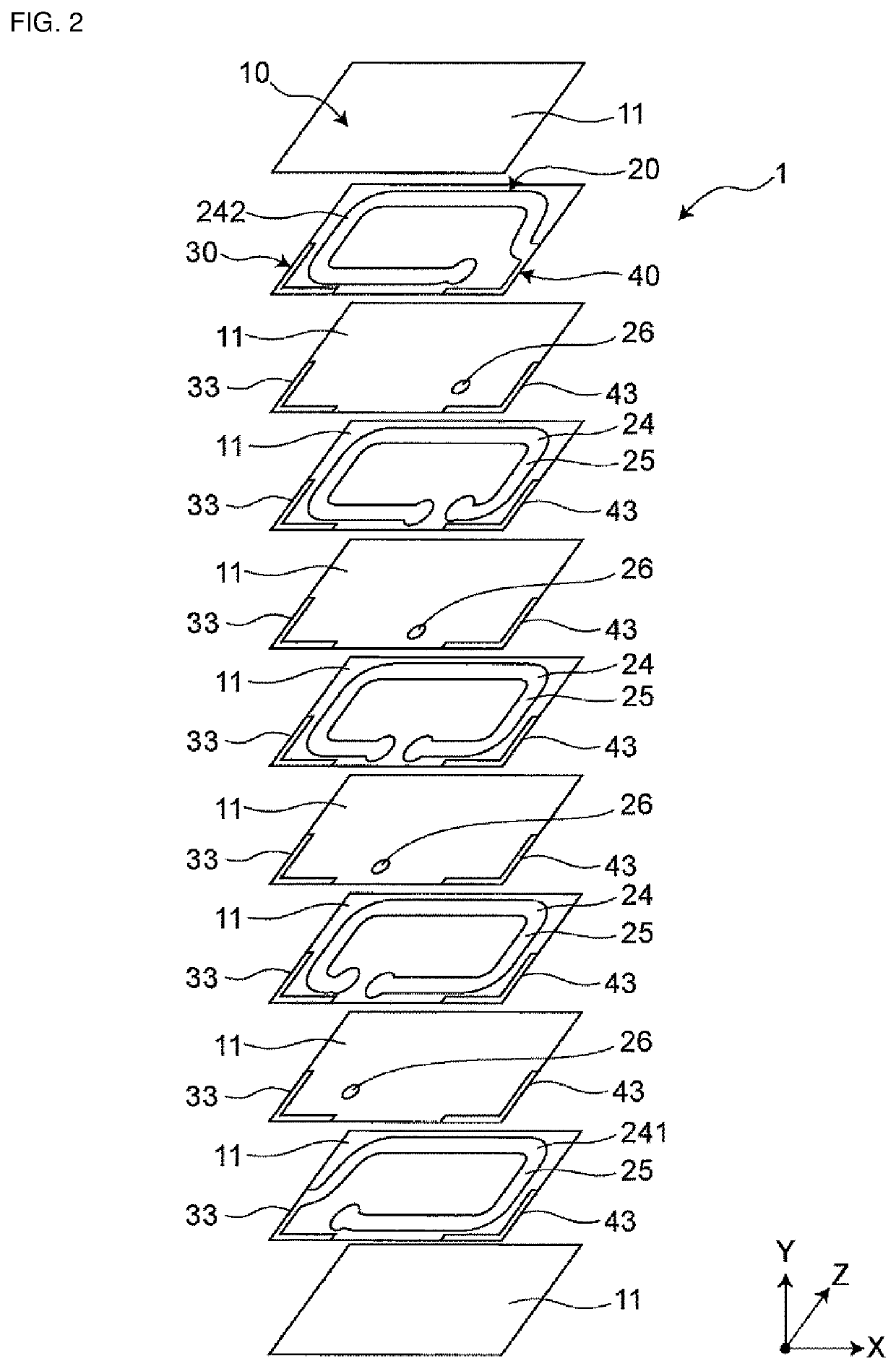
[0034]FIG. 1 is a see-through perspective view showing a first embodiment of an inductor component. FIG. 2 is an exploded perspective view of the inductor component. As shown in FIGS. 1 and 2, an inductor component 1 has an element assembly 10, a coil 20 which is provided inside the element assembly 10 and is helically wound along an axis, and a first outer electrode 30 and a second outer electrode 40 which are provided in the element assembly 10 and are electrically connected to the coil 20. Although the element assembly 10 is drawn in FIG. 1 as transparent for easy understanding of a structure thereof, the element assembly 10 may be semitransparent or opaque.

[0035]The inductor component 1 is electrically connected to wiring of a circuit board (not shown) via the first and second outer electrodes 30 and 40. The inductor component 1 is used as, for example, a coil (matching coil) for impedance matching of a high-frequency circuit and is used in electronic equipment, such as a person...

second embodiment

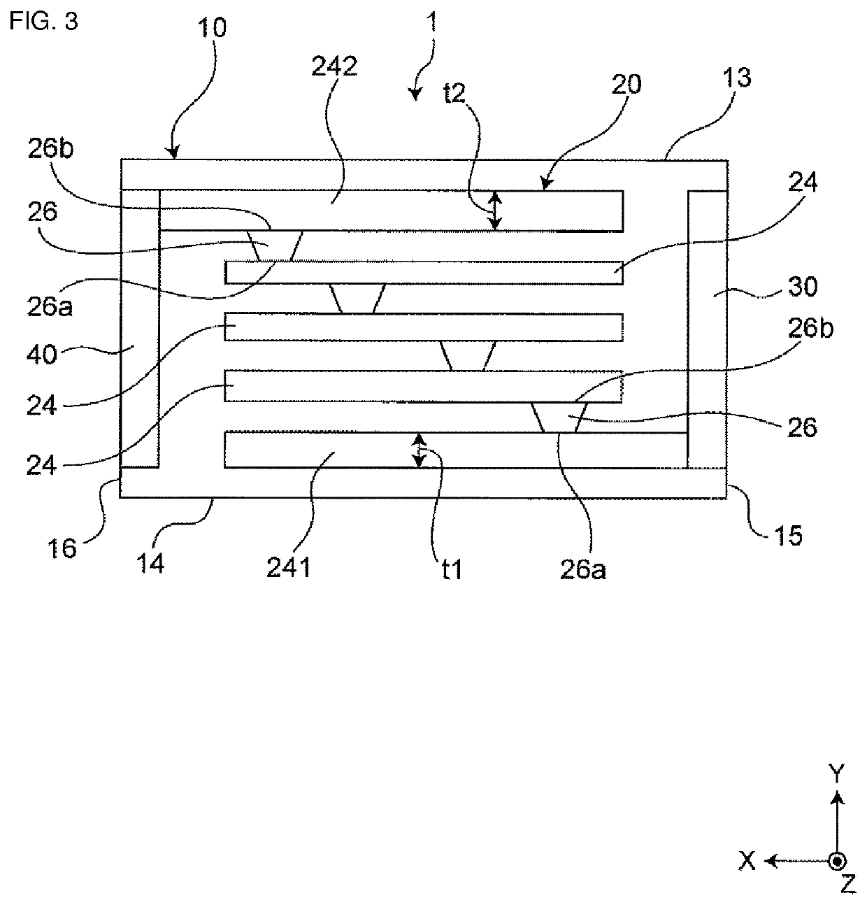
[0060]FIG. 5 is a see-through plan view as viewed from above showing a second embodiment of the inductor component. The second embodiment is different in the number of layers of coil conductor layers of coil wiring from the first embodiment. Different components will be described below. The other components are the same as the first embodiment, the components are denoted by identical reference characters in the first embodiment, and a description thereof will be omitted. Note that the number of layers of pieces of coil wiring 24A is drawn in FIG. 5 as smaller than the number of layers of pieces of coil wiring in FIG. 3, for convenience's sake.

[0061]As shown in FIG. 5, in a coil 20A of an inductor component 1A according to the second embodiment, each coil wiring 24A is composed of a plurality of coil conductor layers 25. In each coil wiring 24A, the plurality of coil conductor layers 25 are stacked along an axis and are electrically connected in parallel. Although the plurality of co...

third embodiment

[0069]FIG. 6 is a see-through front view as viewed from a first side surface showing a third embodiment of the inductor component. The third embodiment is different in a configuration of an extended portion of a coil from the first embodiment. Different components will be described below. The other components are the same as the first embodiment, the components are denoted by identical reference characters in the first embodiment, and a description thereof will be omitted.

[0070]As shown in FIG. 6, in a coil 20B of an inductor component 1B according to the third embodiment, a first extended portion 21 is connected between a first end 23a of a wound portion 23 and a first outer electrode 30, and a second extended portion 22 is connected between a second end 23b of the wound portion 23 and a second outer electrode 40. Since the wound portion 23 is a portion, parts of which overlap with each other when viewed in a direction parallel to an axis and which is helically wound, the first end...


PUM


Abstract

An inductor component includes an element assembly; a coil inside the element assembly and helically wound along an axis; and first and second outer electrodes in the element assembly and electrically connected to the coil. The element assembly has insulating layers stacked along the axis. The coil has pieces of coil wiring stacked along the axis and via wiring extending along the axis and connecting the pieces of coil wiring adjacent in a direction of the axis. The pieces are each wound along a plane, are electrically connected in series in a helix, and have first and second coil wirings at a respective endmost on one and other sides in a direction parallel to the axis and respectively connected to the first and second outer electrodes. An end surface on the one side has an area smaller than that of an end surface on the other side.

Description

CROSS-REFERENCE TO RELATED APPLICATION[0001]This application claims benefit of priority to Japanese Patent Application No. 2021-027471, filed Feb. 24, 2021, the entire content of which is incorporated herein by reference.BACKGROUNDTechnical Field[0002]The present disclosure relates to an inductor component.Background Art[0003]Conventional inductor components include one disclosed in Japanese Unexamined Patent Application Publication No. 2015-015297. The inductor component has an element assembly, a coil which is provided inside the element assembly and is helically wound along an axis, and two outer electrodes which are provided on the element assembly and are electrically connected to the coil. The element assembly has a plurality of insulating layers which are stacked along the axis. The coil has a plurality of pieces of coil wiring which are stacked along the axis. The plurality of pieces of coil wiring are each wound along a plane, and are electrically connected in series to con...

Claims


Application Information

Patent Timeline
IPC IPC(8): H01F17/00H01F27/29
CPCH01F17/0013H01F27/292H01F27/29H01F27/2804H01F2027/2809H01F2017/004
Inventor TAKAHASHI, DAISUKE
Owner MURATA MFG CO LTD
Why Eureka
Try Eureka