Miniaturized connector

a connector and miniaturized technology, applied in the direction of two-part coupling devices, coupling device connections, electric discharge tubes, etc., can solve the problems of low connection reliability and electric performance, and achieve the effect of short-circuiting between terminals and remarkable productivity improvemen

Inactive Publication Date: 2004-12-09
ASO AKIRA +2
View PDF4 Cites 5 Cited by
  • Summary
  • Abstract
  • Description
  • Claims
  • Application Information

AI Technical Summary

Benefits of technology

[0008] Accordingly, an object of the present invention is to provide a technology of a connector, in which, without the increase of the number of existing manufacturing steps and the need of other parts, short-circuiting between terminals can be realized considerably efficiently, thereby enhancing productivity remarkably.
[0010] According to the present invention, the continuous portion for short-circuit between both the terminals is formed as a part of the metal plate which remains during the punching, or other manufacturing, process for both the terminals, and therefore a new step of forming the continuous portion is not required. Consequently, the formation of the continuous portion can be realized extremely efficiently without the increase of the number of the existing manufacturing steps and the need of other parts. Due to this, the productivity can be remarkably enhanced. Further, the soldered portion is not increased, so that a structure in which a factor that may lower the connection reliability, lower the electric performance, or the like is not added, can be provided.

Problems solved by technology

Further, the soldered portion is not increased, so that a structure in which a factor that may lower the connection reliability, lower the electric performance, or the like is not added, can be provided.

Method used


Image

  • Miniaturized connector
  • Miniaturized connector
  • Miniaturized connector

Examples


Embodiment Construction

[0028] While the invention may be susceptible to embodiment in different forms, there is shown in the drawings, and herein will be described in detail, a specific embodiment with the understanding that the present disclosure is to be considered an exemplification of the principles of the invention, and is not intended to limit the invention to that as illustrated and described herein.

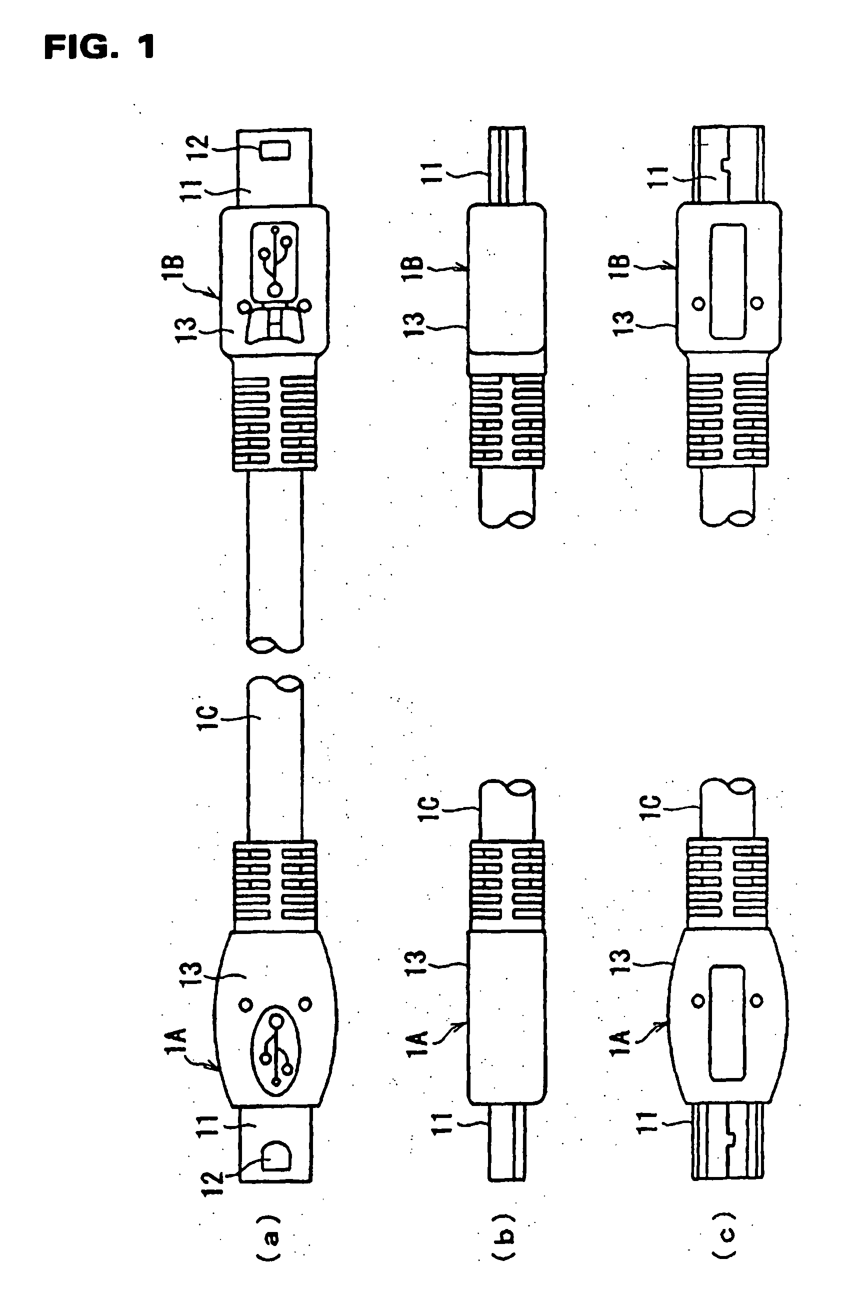
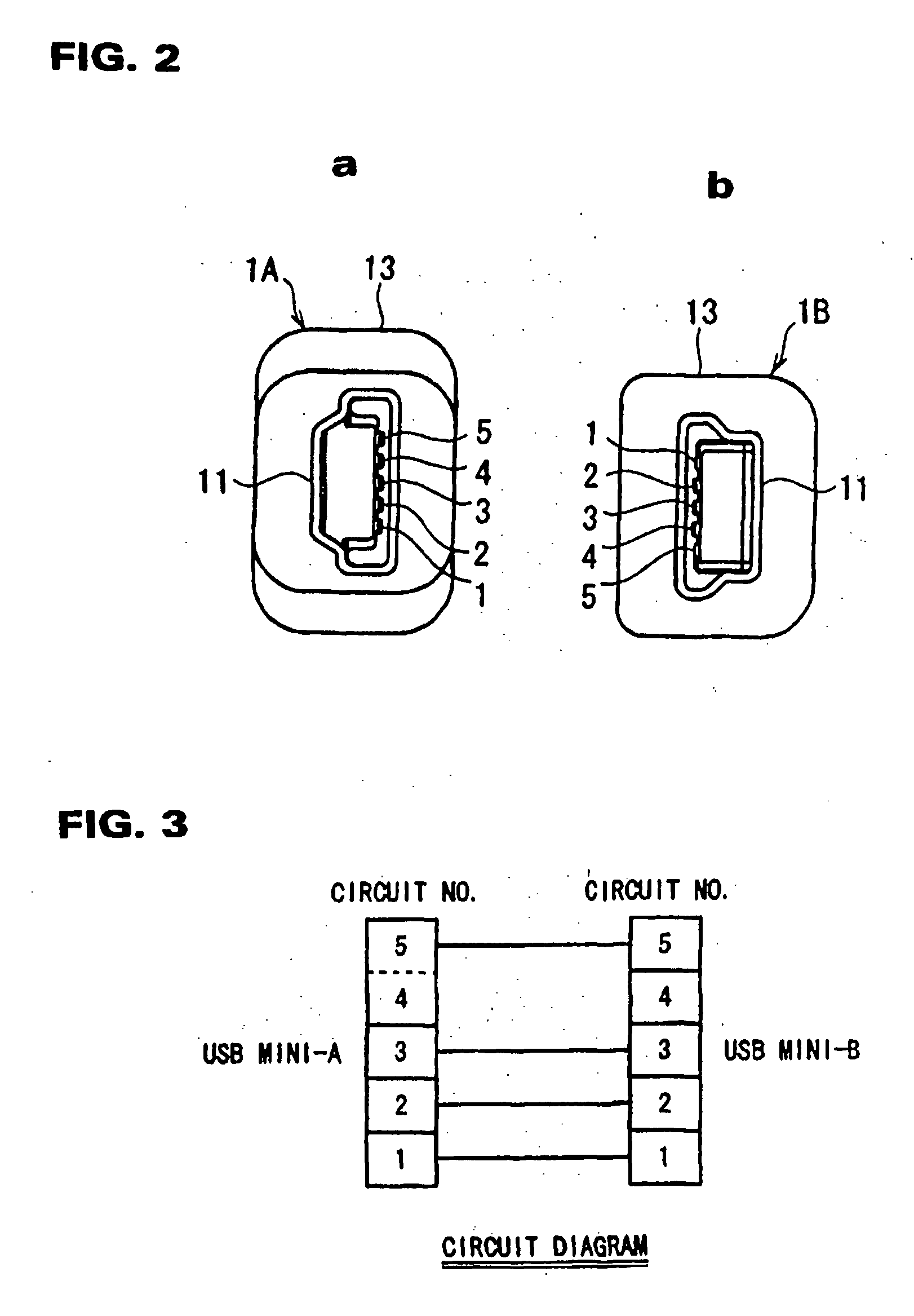
[0029] Hereafter, an embodiment of the present invention will be described with reference to FIGS. 1 to 11. FIG. 1(a) is a plane view showing an embodiment in which an A type plug connector 1A is provided on one end side of a cable 1C, and a B type plug connector 1B is provided on the other end side thereof. FIG. 1(b) is a side view of each plug connector 1A, 1B with a portion of the cable 1C being omitted, and FIG. 1(c) is a bottom view thereof. FIG. 2(a) is an end surface view of the plug connector 1A shown in FIG. 1, and FIG. 2(b) is an end surface view of the plug connector 1B shown in FIG. 1. Each ...


PUM


Abstract

The present invention is directed to an electrical connector having at least two terminals that are short-circuited to each other by the use of a continuous portion. The continuous portion is formed during the manufacturing process of the terminals, thereby simplifying short-circuiting of two or more terminals together.

Description

[0001] The present invention relates to short circuiting terminals of a connector, and in particular, to a miniaturized USB type connector having two of its terminals short circuited together which is used in equipment requiring a smaller connector, such as portable electronic equipment[0002] A USB (Universal Serial Bus) connector is generally known. Recently, portable equipment, such as digital cameras, cellular phones and PDAs (Portable Digital Assistant) have been used widely, and thus the USB connector has been miniaturized.[0003] This miniature USB connector is approximately 1 / 8 the size of a conventional USB connector. Because of this small size, it is highly desirable for use in portable electronic equipment. This connector has five terminals, in which an ID terminal for identification of host equipment is assembled in addition to conventional signal lines.[0004] Currently, there are two forms of miniature USB type connectors, called an "A" type and a "B" type, or also known ...

Claims


Application Information

Patent Timeline
Patent Type & Authority Applications(United States)
IPC IPC(8): H01R31/08
CPCH01R31/08
Inventor ASO, AKIRASASAO, MASAMITAKAHASHI, KAZUYA
Owner ASO AKIRA
Why Eureka
Try Eureka