
Semiconductor testkey pattern and test method thereof

a testkey and semiconductor technology, applied in semiconductor/solid-state device testing/measurement, reference comparison, instruments, etc., can solve problems such as inconsistent sound on the left and right sides of headphones, affecting the quality of subsequent electronic products, etc., to improve process yield and efficiency.

Active Publication Date: 2022-09-08
UNITED SEMICONDUCTOR (XIAMEN) CO LTD
View PDF6 Cites 0 Cited by
  • Summary
  • Abstract
  • Description
  • Claims
  • Application Information

AI Technical Summary

Benefits of technology

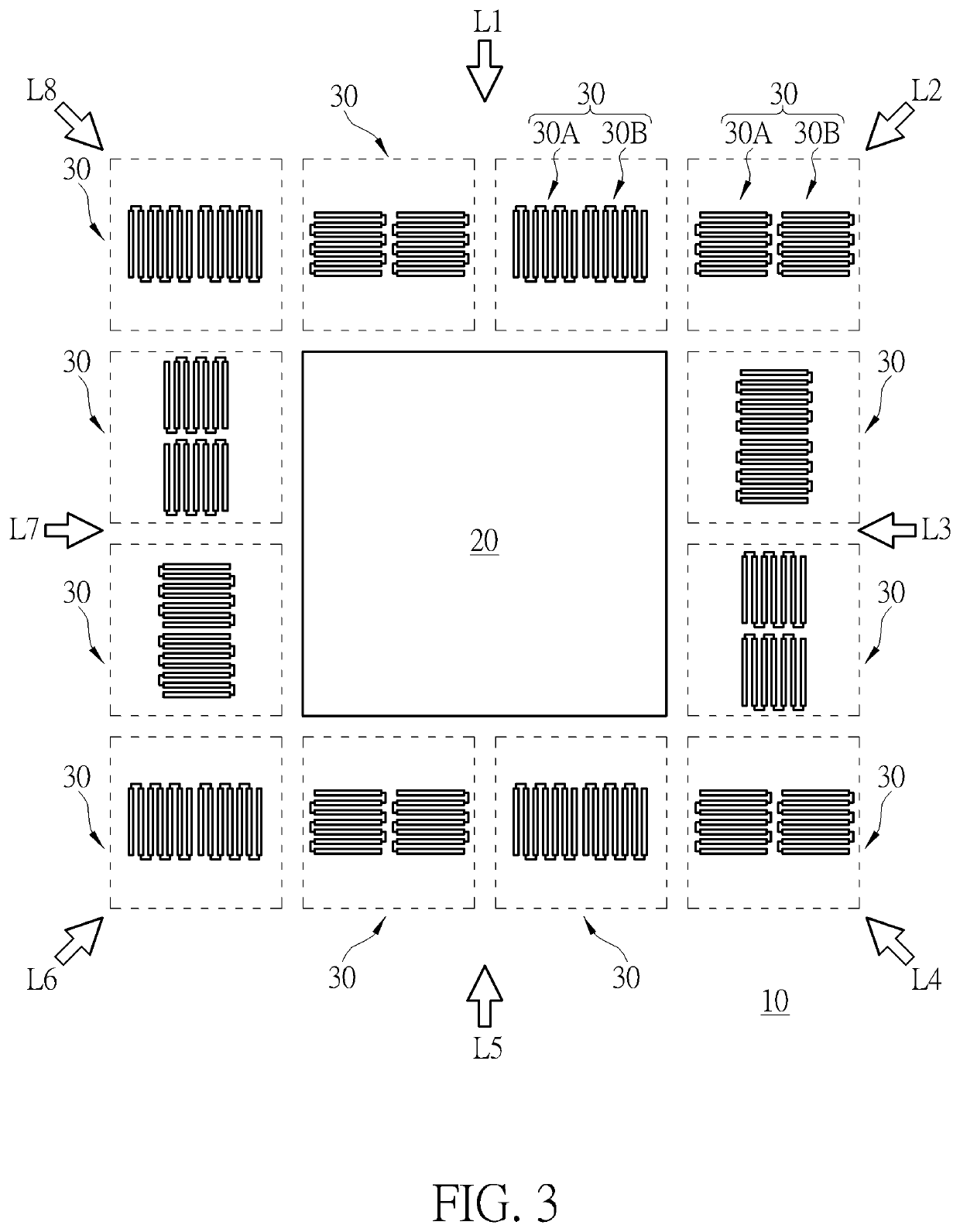
The invention provides a semiconductor test key pattern that helps to quickly identify and fix problems during the laser heating step in the manufacturing process of semiconductors. By using this test key pattern, the applicant can better understand the impact of hot spots on the resistance value of resistors in the device region. The semiconductor test key pattern can be applied in different directions and can help to find the most suitable process parameters. This way, unpaired resistors can be caught and corrected in time, improving the yield and efficiency of the process.

Problems solved by technology

However, even if the paired resistors have the same or symmetrical patterns, some of the steps in the semiconductor manufacturing process may affect the resistance values of the resistors, resulting in unequal resistance values on both sides of the paired resistors, and affecting the quality of subsequent electronic products (for example, causing inconsistent sounds on the left and right sides of headphones).

Method used


Image

  • Semiconductor testkey pattern and test method thereof
  • Semiconductor testkey pattern and test method thereof
  • Semiconductor testkey pattern and test method thereof

Examples


Embodiment Construction

[0013]To provide a better understanding of the present invention to users skilled in the technology of the present invention, preferred embodiments are detailed as follows. The preferred embodiments of the present invention are illustrated in the accompanying drawings with numbered elements to clarify the contents and the effects to be achieved.

[0014]Please note that the figures are only for illustration and the figures may not be to scale. The scale may be further modified according to different design considerations. When referring to the words “up” or “down” that describe the relationship between components in the text, it is well known in the art and should be clearly understood that these words refer to relative positions that can be inverted to obtain a similar structure, and these structures should therefore not be precluded from the scope of the claims in the present invention.

[0015]One object of the present invention is to design a semiconductor testkey pattern for observin...


PUM

PropertyMeasurementUnit
included angleaaaaaaaaaa
distanceaaaaaaaaaa
distanceaaaaaaaaaa

Abstract

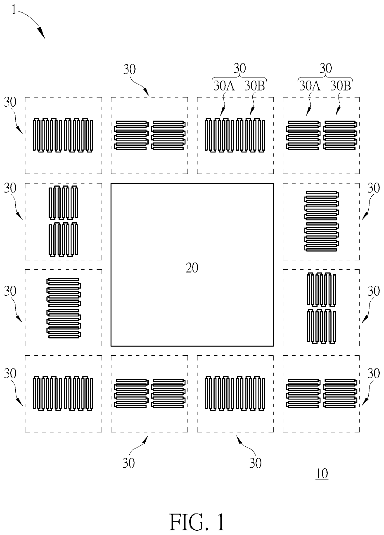
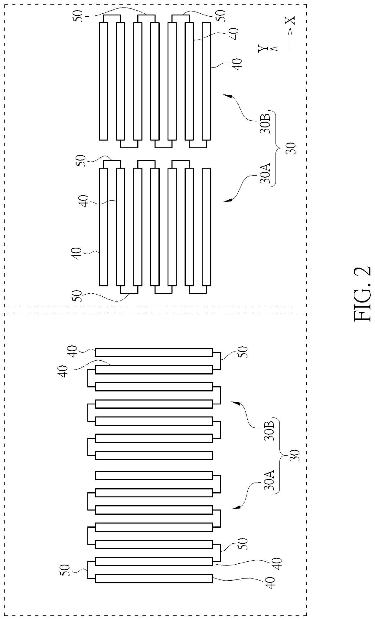
The invention provides a semiconductor testkey pattern, the semiconductor testkey pattern includes a high density device region and a plurality of resistor pairs surrounding the high density device region, wherein each resistor pair includes two mutually symmetrical resistor patterns.

Description

BACKGROUND OF THE INVENTION1. Field of the Invention[0001]The present invention relates to the field of semiconductor manufacturing processes, in particular to a semiconductor testkey pattern including a plurality of resistor pair.2. Description of the Prior Art[0002]In the field of semiconductor manufacturing, resistor are common electronic components. In some practical applications, resistors are made in pairs to be used in electronic products that are also paired, such as headphones.[0003]However, even if the paired resistors have the same or symmetrical patterns, some of the steps in the semiconductor manufacturing process may affect the resistance values of the resistors, resulting in unequal resistance values on both sides of the paired resistors, and affecting the quality of subsequent electronic products (for example, causing inconsistent sounds on the left and right sides of headphones).SUMMARY OF THE INVENTION[0004]Therefore, it is necessary to provide an improved method t...

Claims


Application Information

Patent Timeline
Patent Type & Authority Applications(United States)
IPC IPC(8): H01L21/66G01R27/02
CPCH01L22/34G01R27/02H01L27/0611H01L22/14H01L22/30H01L21/268G01R27/14G01R17/105G01R31/2831G01R31/2858G01R27/2635
Inventor YUAN, LINSHANYANG, GUANGOUYANG, JINJIANLYU, JIAWEIHUANG, CHIN-CHUNTAN, WEN YI
Owner UNITED SEMICONDUCTOR (XIAMEN) CO LTD
Learn More