A Beverage Dispense Apparatus and Method Relating to Same

a beverage and keg technology, applied in the direction of liquid dispensing, packaging, transportation and packaging, etc., can solve the problems of not always possible for a bar or similar outlet to store beverages in bulk containers, and the space needed for storing kegs is significant. to achieve the effect of preserving the quality of the head

Pending Publication Date: 2022-09-15
DIAGEO IRELAND UNLIMITED CO
View PDF13 Cites 0 Cited by
  • Summary
  • Abstract
  • Description
  • Claims
  • Application Information

AI Technical Summary

Benefits of technology

[0022]Dispense speed may be controlled by gas pressure of the delivery device. Indeed, dispense may be stopped / paused in order to allow a settle time of the beverage before restarting dispense and delivering a final volume. Such control may be achieved by used of a vacuum configured pump. A vacuum step may also be applied at completion of filling a vessel to preserve the quality of the head.

Problems solved by technology

Draught dispense is generally only possible in a public house / restaurant environment since dispense equipment is expensive and requires maintenance.
Of course, it is not always possible for a bar or similar outlet to store beverages in bulk containers such as kegs, due to space and cost constraints.
The space needed to store kegs is significant, and the associated dispensing and chilling equipment also involves significant cost for the proprietor and may not be justified where there is a relatively low volume of sales.
A creamer plate is not desirable in the context of a lager or other purely carbonated beverage because it causes excessive frothing and a head which is too large and obstructive for comfortable consumption.
Use of conventional single unit packaging cannot reproduce the head of a draught dispense system unless an additional device / feature is employed to mimic the effect.
Widgets are widely available and accepted in the marketplace but add an expense / delay to the manufacturing process along with resultant plastic waste as the widget is left behind in a used beverage container.

Method used


Image

  • A Beverage Dispense Apparatus and Method Relating to Same
  • A Beverage Dispense Apparatus and Method Relating to Same
  • A Beverage Dispense Apparatus and Method Relating to Same

Examples


Embodiment Construction

[0029]The following description presents exemplary embodiments and, together with the drawings, serves to explain principles of the invention. However, the scope of the invention is not intended to be limited to the precise details of the embodiments, since variations will be apparent to a skilled person and are deemed also to be covered by the description. Terms for components used herein should be given a broad interpretation that also encompasses equivalent functions and features. In some cases, several alternative terms (synonyms) for structural features have been provided but such terms are not intended to be exhaustive.

[0030]Descriptive terms should also be given the broadest possible interpretation; e.g. the term “comprising” as used in this specification means “consisting at least in part of” such that interpreting each statement in this specification that includes the term “comprising”, features other than that or those prefaced by the term may also be present. Related term...


PUM


Abstract

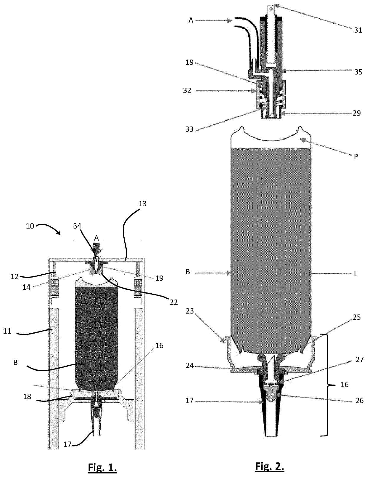
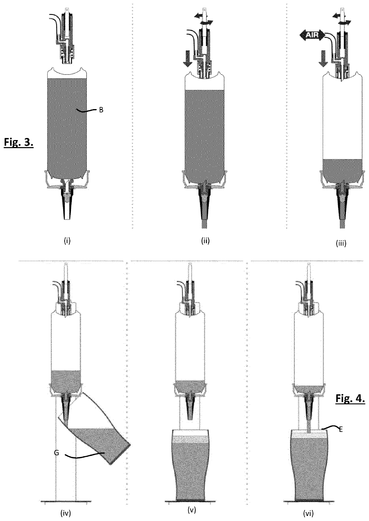
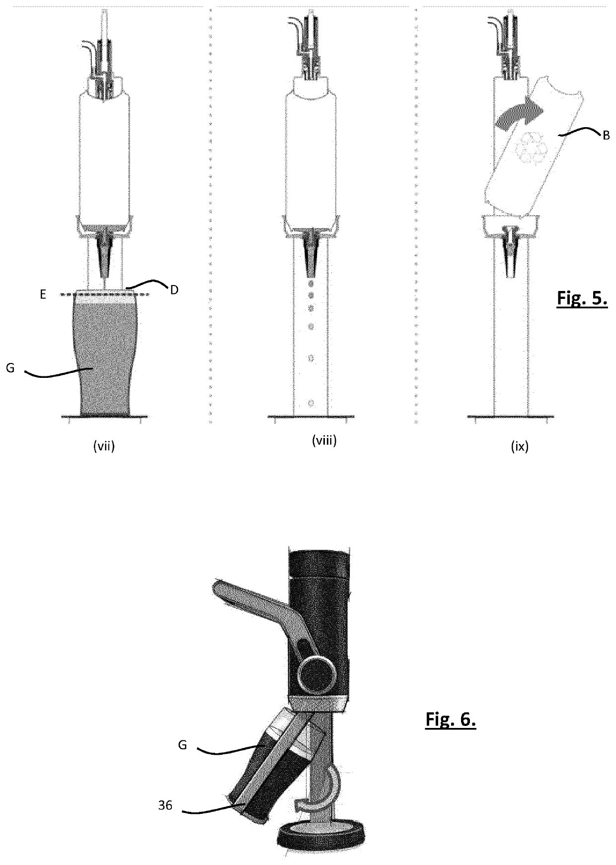
An apparatus (10) and method for dispensing beverage from a single serve beverage package (b), e.g. an aluminium can B. In operation the sealed package (B) is located and held in a receiving enclosure (11) where, firstly, a dispense end of the package is opened by a piercing element (24) and, secondly, a gas is introduced under pressure at a second end through a hollow needle (19). Gas from a pump, into the internal volume of package (B), is then used to drive beverage from the beverage package, e.g. through a restrictor structure (27), at the dispense end and into a drinking vessel (G). The pump mode may then apply negative pressure to prevent flow and enable a pause in flow or at completion of delivery to a vessel (G).

Description

TECHNICAL FIELD[0001]The present invention relates to a method and apparatus for beverage dispense. The method and apparatus replicates draught dispense in a compact device and in one form enables forming of a head on the beverage during / following the dispense process. Such a beverage will have gas in solution such as carbon dioxide, nitrogen, a combination thereof or any other inert gas suitable for the purpose. The beverage may be alcoholic or non-alcoholic, but the present invention is particularly suited for use with beverages such as cider, cocktails, beer, lager, ale and stout, where the presence of a head on the beverage when it is presented to the consumer in a drinking vessel is traditional and desirable.BACKGROUND TO THE INVENTION[0002]The most common form of beer delivery to a consumer is by way of a draught dispenser from a keg (i.e. a large volume / bulk container with multiple servings) or single unit packages such as aluminium cans and glass bottles. Draught dispense is...

Claims


Application Information

Patent Timeline
Patent Type & Authority Applications(United States)
IPC IPC(8): B67D1/06B67D1/04B67D1/08
CPCB67D1/06B67D1/0425B67D1/0894B67D1/0891B67D2001/0098B67D1/04B67D1/0412B67B7/28B67D1/1275
Inventor MURPHY, CHRISTOPHERHENDRON, STEPHENKILCULLEN, STEPHENRYAN, JAMES
Owner DIAGEO IRELAND UNLIMITED CO
Why Eureka
Try Eureka