Eureka AIR delivers breakthrough ideas for toughest innovation challenges, trusted by R&D personnel around the world.

Gas turbine fuel mixer comprising a plurality of mini tubes for generating a fuel-air mixture

Pending Publication Date: 2022-09-15
GENERAL ELECTRIC CO
View PDF17 Cites 0 Cited by
  • Summary
  • Abstract
  • Description
  • Claims
  • Application Information

AI Technical Summary

Benefits of technology

The patent describes a method for mixing fuel in a gas turbine engine. The method involves injecting natural gas fuel into the engine and then adding a percentage of hydrogen fuel into a mixer to create a fuel blend. The hydrogen fuel is then added gradually to the mixer to achieve a mixture of 70-90% hydrogen fuel. This method helps to reduce emissions by mixing the fuel blend effectively and minimizing the formation of low-velocity pockets in the mixer. The technical effect of this method is cleaner and more efficient operation of the gas turbine engine.

Problems solved by technology

Presently, gas turbine engines are not capable of burning high hydrogen fuel blends.
Mixers of the gas turbine engines present low-velocity pockets within the mixer that result in flashback (e.g., flame returning to the mixer) and flame-holding issues (e.g., flame within mixer), additionally fuel-air needs to be well mixed before exiting mixer to ensure lower NOx emission.

Method used


Image

  • Gas turbine fuel mixer comprising a plurality of mini tubes for 
generating a fuel-air mixture
  • Gas turbine fuel mixer comprising a plurality of mini tubes for 
generating a fuel-air mixture
  • Gas turbine fuel mixer comprising a plurality of mini tubes for 
generating a fuel-air mixture

Examples


Embodiment Construction

[0026]Various embodiments of the preferred embodiments are discussed in detail below. While specific embodiments are discussed, this is done for illustration purposes only. A person skilled in the relevant art will recognize that other components and configurations may be used without departing from the spirit and scope of the disclosure.

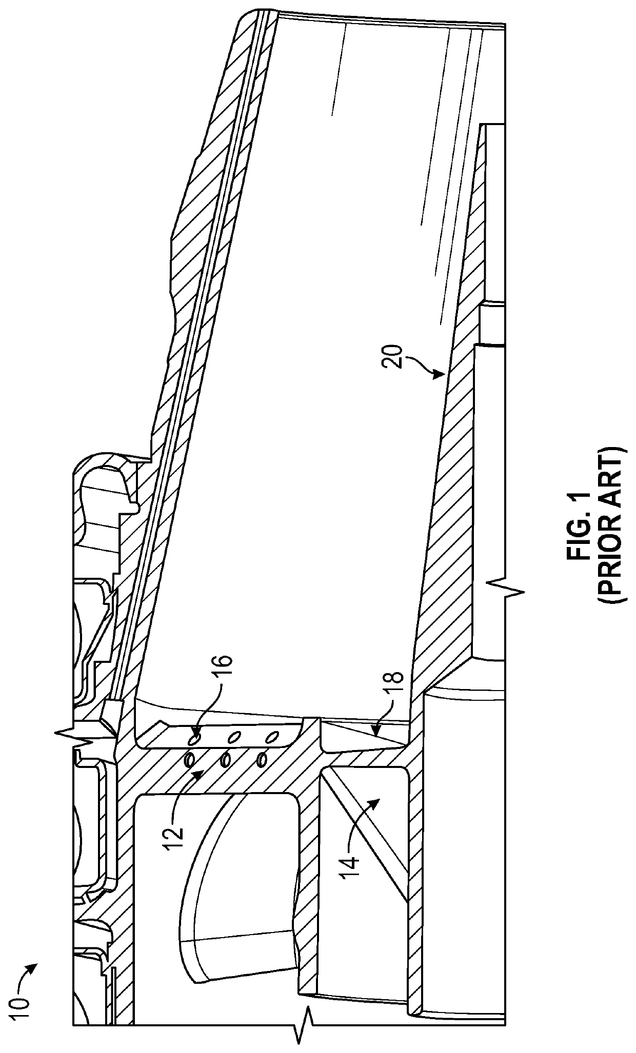
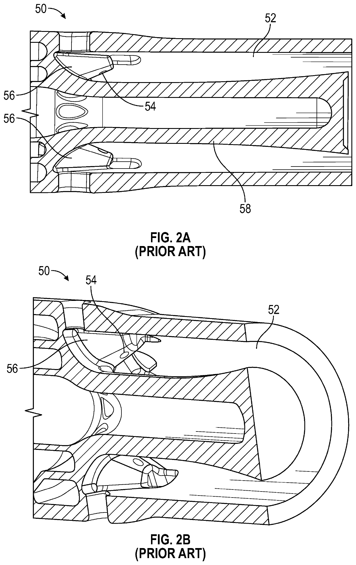
[0027]The mixer of the present disclosure is presented in the combustion section of a gas turbine engine. The mixer may blend or mix the fuel and air prior to combustion. The mixer of the present disclosure may also be known as a premixer. The mixer may reduce carbon emissions by allowing burn of pure hydrogen fuel (e.g., 100% hydrogen fuel) or a blend of hydrogen fuel and natural gas (e.g., having a hydrogen percentage between 0% and 100%) through enhanced mixing with little or no low-velocity regions and no flashback conditions. The mixer of the present disclosure provides for a mixer that may blend fuel and air in order to achieve a uniform fuel-...


PUM


Abstract

A mixer for blending fuel and air in a combustor of a turbine engine. The mixer includes a central body having a central passageway and a central axis. The mixer includes a plurality of tubes positioned radially around the central axis and circumferentially around a periphery of the mixer. Each of the tubes of the mixer includes opposed openings and a tangential opening. Each of the tubes of the mixer includes a cylindrical interior mixing passage configured to receive air flow from the opposed openings and the tangential opening and a fuel flow. The opposed openings are configured to spread the fuel flow laterally and the tangential opening is configured to spread the fuel flow tangentially.

Description

TECHNICAL FIELD[0001]The preferred embodiments relate to a fuel mixer. More particularly, the preferred embodiments relate to a hydrogen fuel mini mixer with confined tube cluster.BACKGROUND[0002]Presently, gas turbine engines are not capable of burning high hydrogen fuel blends. Mixers of the gas turbine engines present low-velocity pockets within the mixer that result in flashback (e.g., flame returning to the mixer) and flame-holding issues (e.g., flame within mixer), additionally fuel-air needs to be well mixed before exiting mixer to ensure lower NOx emission.BRIEF SUMMARY[0003]According to an embodiment, a mixer for blending fuel and air in a combustor of a gas turbine engine, the mixer comprising: a central body having a central passageway and a central axis; a plurality of tubes positioned radially around the central axis and circumferentially around a periphery of the mixer, each of the tubes comprising: a first opening angled with respect to the central axis and configured...

Claims


Application Information

Patent Timeline
IPC IPC(8): F23R3/28F02C7/22F23R3/12
CPCF23R3/286F02C7/222F23R3/12F23R3/343F23R2900/00002F02C3/20F23R3/36F02C7/26
Inventor NAIK, PRADEEPGIRIDHARAN, MANAMPATHY G.KEDIYA, VISHAL SANJAYBOARDMAN, GREGORY A.
Owner GENERAL ELECTRIC CO
Why Eureka
Eureka Blog
Learn More