A coin feeding unit, a module comprising said coin feeding unit, and a coin handling machine

a coin feeding unit and coin feeding technology, applied in coin dispensers, coin counters, instruments, etc., can solve the problems of coins directly leaving the coin feeding unit, damage to the discharge gate and/or its opening mechanism, and the management of unwanted objects

Pending Publication Date: 2022-09-15
SCAN COIN
View PDF0 Cites 0 Cited by
  • Summary
  • Abstract
  • Description
  • Claims
  • Application Information

AI Technical Summary

Benefits of technology

[0015]The coin feeding unit of the present disclosure may present several advantages. In the manner described above, the discharge gate of the coin feeding unit may be less prone to having coins or unwanted objects getting stuck between the gate and the opening in the coin guiding arrangement, when attempting to close the discharge gate. Furthermore, with a hinged gate, there is a risk that the gate is accidentally being pushed open by the weight of the coins in the coin guiding arrangement. With the present discharge gate being slidably arranged, the gate is not allowed to move in the direction of the force exerted by the coin mass onto the gate, eliminating the risk of the gate being opened accidentally. By the present arrangement, a coin feeding unit with a discharge gate may be provided, wherein the discharge gate exhibits a lower risk of jamming and wherein the risk of accidentally opening the discharge gate by the weight of the material in the coin guiding arrangement, pushing the gate downwards, is eliminated, or at least reduced. Furthermore, a slidably arranged discharge gate can be made larger than a hinged gate without sacrificing functionality and / or structural integrity. This allows for a faster and more efficient discharge of unwanted objects from the coin guiding arrangement. The slidably arranged discharge gate may also be made more durable and strong than the hinged gate. Thus, the slidably arranged discharge gate may withstand higher impact and pressure from unwanted objects and coins than the hinged gate. This may be especially important in the occasion of a gate jam, where forces exerted on the discharge gate and / or transmission mechanics can be high and potentially damaging.
[0047]By the present arrangement the force pulling the discharge gate is more evenly distributed across the width of the discharge gate. This prevents the discharge gate from being jammed during displacement of the discharge gate. Specifically, this may be of importance in embodiments where the discharge gate is slidably arranged in the coin guiding arrangement in a pair of opposed elongated grooves.

Problems solved by technology

A problem with this particular kind of coin feeding machine is that a user, when depositing the mass of coins in the coin input hopper of the machine, sometimes manages to deposit also unwanted objects such as buttons, rings, stones or the like.
The unwanted objects will end up in the temporary storage together with the mass of coins but, contrary to the coins, the unwanted objects will not leave the coin hopper by the coin transport unit, as said unit is incapable of picking up the unwanted objects due to their geometrical shape.
A problem with these kind of coin feeding units is, however, that unwanted objects, and coins, sometimes get stuck in, or jams the discharge gate such that it is only partially closed, risking to damage the discharge gate and / or its opening mechanism.
This may result in the coins directly leaving the coin feeding unit.
Furthermore, with a hinged gate, there is a risk that the gate is accidentally being pushed open by the weight of the coins in the coin guiding arrangement.
This may be especially important in the occasion of a gate jam, where forces exerted on the discharge gate and / or transmission mechanics can be high and potentially damaging.
However, it is also conceivable that the displacement path extends nonlinearly.
For alternative embodiments of the coin feeding unit, wherein the drive unit is configured to actively close the discharge gate, the drive unit may, in case of a jam in the discharge gate, be stalled, which could risk damaging the drive unit and / or the transmission mechanism.

Method used


Image

  • A coin feeding unit, a module comprising said coin feeding unit, and a coin handling machine
  • A coin feeding unit, a module comprising said coin feeding unit, and a coin handling machine
  • A coin feeding unit, a module comprising said coin feeding unit, and a coin handling machine

Examples


Embodiment Construction

[0069]The present invention will now be described more fully hereinafter with reference to the accompanying drawings, in which currently preferred embodiments of the invention are shown. This invention may, however, be embodied in many different forms and should not be construed as limited to the embodiments set forth herein; rather, these embodiments are provided for thoroughness and completeness, and fully convey the scope of the invention to the skilled person.

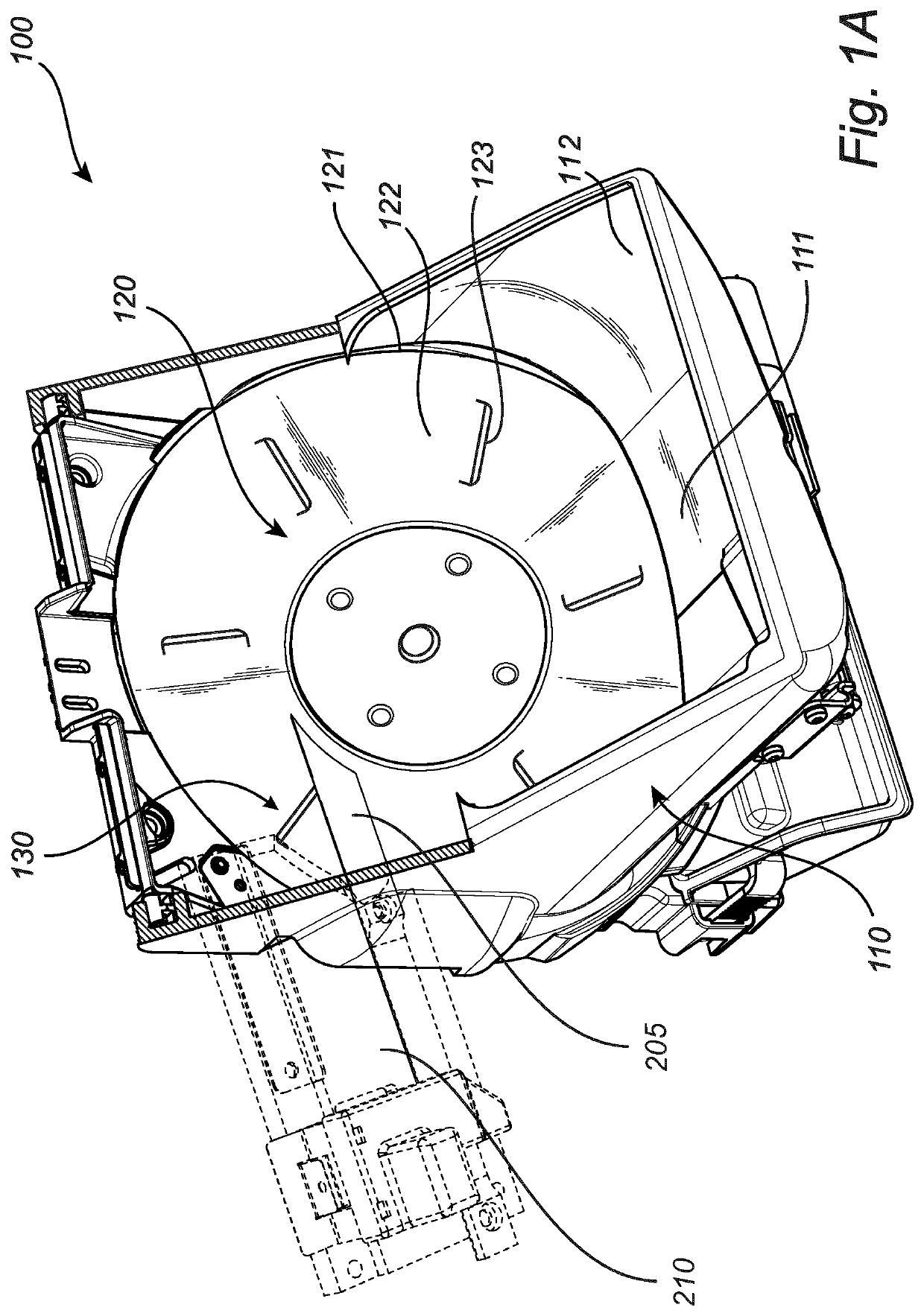
[0070]FIG. 1A illustrates an upper perspective view of a coin feeding unit 100 according to an example embodiment. The coin feeding unit 100 is suitable for feeding a mass of coins received thereto in a disarray fashion, one by one, so as to form an array of coins, to an output position 130. At the coin output position 130, the coins are guided away from the coin feeding unit 100 by means of a separating knife 205. Typically, the coin feeding unit 100 is part of a coin handling machine. Such machines are discussed more in d...


PUM


Abstract

The disclosure relates to a coin feeding unit for a coin handling machine, the coin feeding unit comprising: a coin guiding arrangement, and a coin transport arrangement defining a movable transport surface, wherein said coin guiding arrangement is configured to receive coins and to guide said received coins to an inner coin arrival surface of the coin guiding arrangement, wherein the coin transport arrangement is configured to move said coins, on the movable transport surface, from the coin arrival surface to a coin output position, wherein a discharge gate is provided in the coin guiding arrangement, at the coin arrival surface, for discharging unwanted objects residing thereon, wherein the discharge gate is slidably arranged in the coin guiding arrangement so as to be displaceable, between a closed position and an open position.

Description

FIELD OF THE INVENTION[0001]The present invention generally relates to coin feeding units for use in coin handling machines, and more specifically, the disclosure relates to a coin feeding unit for feeding a mass of coins to an output position at which individual coins of said mass of coins exit the coin feeding unit one by one.BACKGROUND ART[0002]Coin feeding units are well known in the art. Typically, coin feeding units are provided as one of several units working together within a coin handling machine, such as e.g. a coin depositing and dispensing machine typically provided at banks or large financial institutions. Coin feeding units may also be provided in smaller coin handling machines such as e.g. coin sorting machines. One specific kind of coin feeding unit is capable of receiving a mass of coins at essentially the same time, and feed individual coins of said mass of coins, one by one, to an output position of the coin feeding unit, at which the coins are allowed to leave th...

Claims


Application Information

Patent Timeline
Patent Type & Authority Applications(United States)
IPC IPC(8): G07D9/00
CPCG07D9/008G07D2201/00G07D3/00
Inventor WALLMAN-CARLSSON, VICTORMELIN, HÅKANBENGTSSON, KRISTIANWIGENSTAM, DAN
Owner SCAN COIN
Why Eureka
Try Eureka