
Nasal Mucus Suction Device and Channel Forming Method Thereof

Pending Publication Date: 2022-09-22
AVITA
View PDF9 Cites 1 Cited by
  • Summary
  • Abstract
  • Description
  • Claims
  • Application Information

AI Technical Summary

Benefits of technology

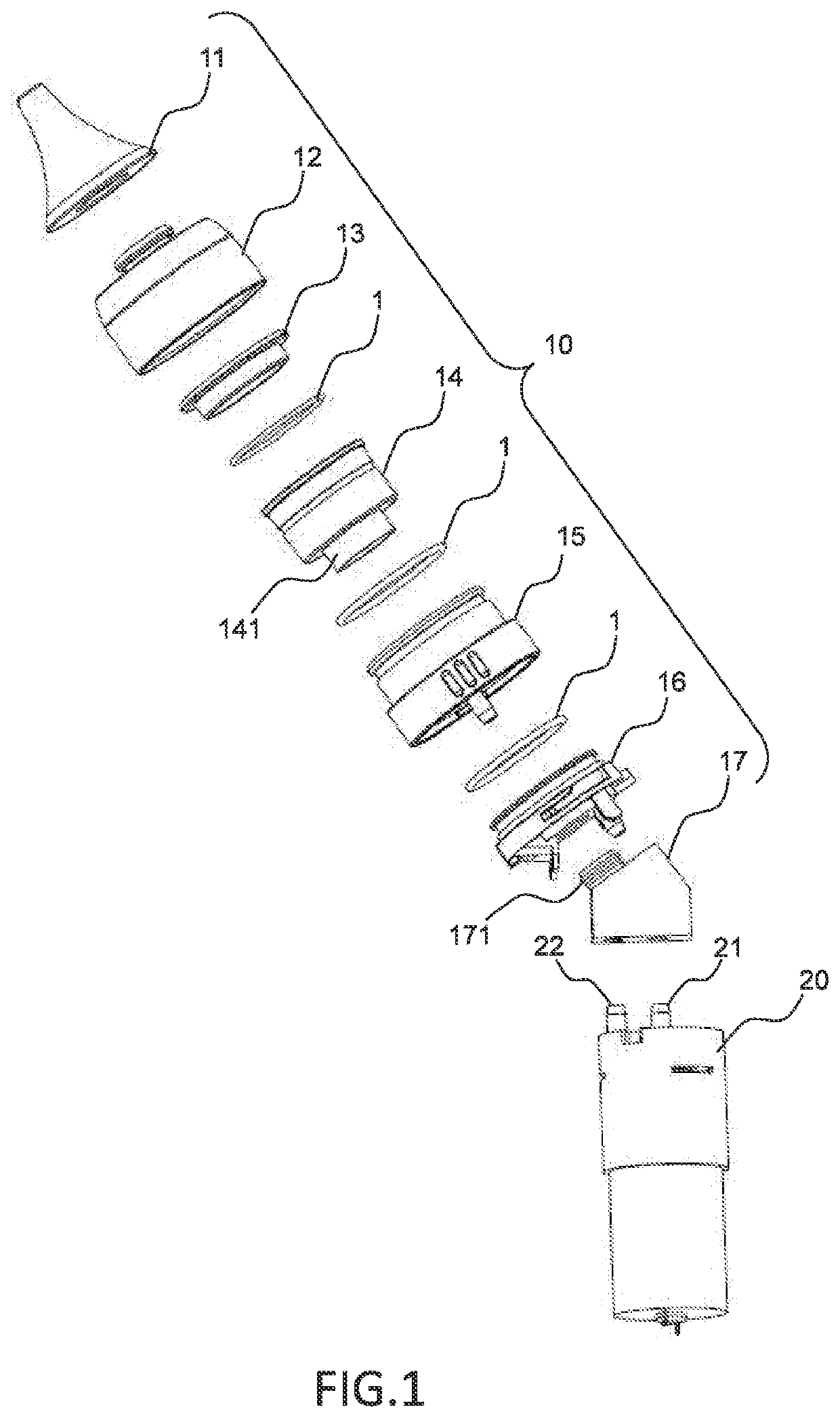
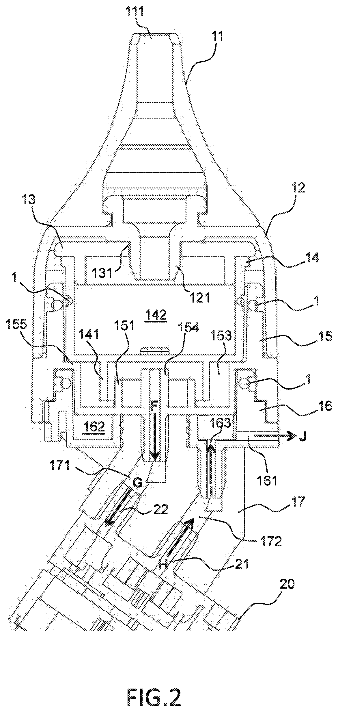
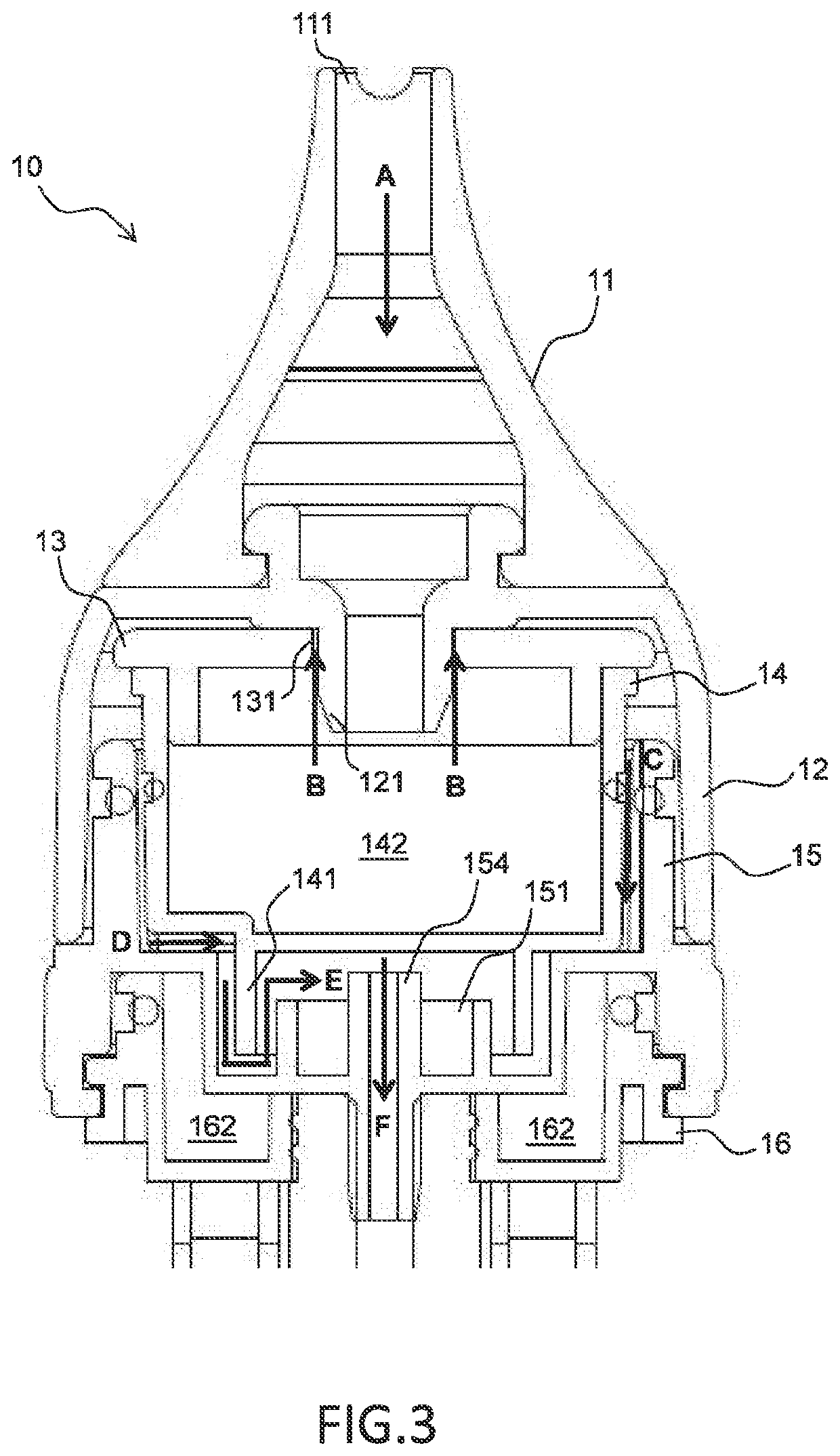
The present invention provides a nasal mucus suction device and a channel forming method with a structure to prevent backflow and overflow of nasal mucus, as well as a noise reduction structure to reduce the noise caused by the air pump. The device includes an air pump and a head structure with a channel between a nasal mucus suction inlet and a gas outlet. The channel includes a first channel section in communication with the nasal mucus suction inlet and a second channel section in communication with the gas outlet. The first channel section has an anti-backflow channel structure and a noise reduction space in the second channel section. The channel forming method includes steps of maximizing a path length of the first channel section and forming curved paths in the first channel section. The device and method can prevent nasal mucus from easily overflowing and reduce the noise caused by the air pump.

Problems solved by technology

According to the conventional technology, the nasal mucus suction device uses an air pump as a power source to generate suction, but unnecessary noise is often caused by the air pump during the operation of the nasal mucus suction device.
In addition, in order to prevent the stored nasal mucus from overflowing, the conventional nasal mucus suction device must have a limitation in a holding angle; however, when the user operates the conventional nasal mucus suction device and rotates the holding angle of the conventional nasal mucus suction device, nasal mucus easily overflows an outer shell of the conventional nasal mucus suction device.

Method used


Image

  • Nasal Mucus Suction Device and Channel Forming Method Thereof
  • Nasal Mucus Suction Device and Channel Forming Method Thereof
  • Nasal Mucus Suction Device and Channel Forming Method Thereof

Examples


Embodiment Construction

[0021]The following embodiments of the present invention are herein described in detail with reference to the accompanying drawings. These drawings show specific examples of the embodiments of the present invention. These embodiments are provided so that this disclosure will be thorough and complete, and will fully convey the scope of the invention to those skilled in the art. It is to be acknowledged that these embodiments are exemplary implementations and are not to be construed as limiting the scope of the present invention in any way. Further modifications to the disclosed embodiments, as well as other embodiments, are also included within the scope of the appended claims.

[0022]These embodiments are provided so that this disclosure is thorough and complete, and fully conveys the inventive concept to those skilled in the art. Regarding the drawings, the relative proportions and ratios of elements in the drawings may be exaggerated or diminished in size for the sake of clarity and...


PUM


Abstract

A nasal mucus suction device includes an air pump and a head structure. The air pump has an intake tube and an outlet tube. The head structure is coupled to the intake tube and the outlet tube of the air pump, and defines a channel between a nasal mucus suction inlet and a gas outlet. The channel includes a first channel section in communication with the nasal mucus suction inlet, and a second channel section in communication with the gas outlet. The first channel section includes at least one mucus storage cavity, the second channel section is in communication with the intake tube and the outlet tube of the air pump. The first channel section has a maximized path length, and includes an anti-backflow channel structure. The second channel section includes a noise reduction space.

Description

BACKGROUND OF THE PRESENT INVENTIONField of Invention[0001]The present invention relates to a nasal mucus suction device. More particularly, the present invention relates to a nasal mucus suction device capable of preventing backflow of nasal mucus and reducing noise, and a channel forming method thereof.Description of Related Arts[0002]Nasal cleaning and medical care are very important clinically, so products with nasal mucus suction functions are developed for cleaning or medical use. Especially in home care, it is necessary to provide simple and quick nasal care including a function of sucking of patient's nasal mucus or phlegm.[0003]According to the conventional technology, the nasal mucus suction device uses an air pump as a power source to generate suction, but unnecessary noise is often caused by the air pump during the operation of the nasal mucus suction device. In addition, in order to prevent the stored nasal mucus from overflowing, the conventional nasal mucus suction de...

Claims


Application Information

Patent Timeline
IPC IPC(8): A61M1/00
CPCA61M1/64A61M1/87A61M2210/0618A61M2202/04A61M2205/42A61M2207/00A61M2205/07A61M2210/005A61M1/78A61M1/65
Inventor OU YANG, HSINGHUANG, JUI-YANGHSIAO, CHING-CHIN
Owner AVITA
Learn More