
A vacuum lifting device

a vacuum lifting and lifting device technology, applied in the direction of manufacturing tools, roads, roads, etc., can solve the problems of manpower lifting, moving and positioning these slabs very difficult, and it is difficult to get a good grip of the slab, so as to avoid slipping or injuring the fingers of people doing this

Pending Publication Date: 2022-09-22
PRITEC VACULYFT AB
View PDF0 Cites 0 Cited by
  • Summary
  • Abstract
  • Description
  • Claims
  • Application Information

AI Technical Summary

Benefits of technology

The present invention provides a way to improve vacuum lifting devices used for lifting and positioning articles. The device has an extendable lifting member that can be actuated to change its length, allowing the device to move between an extended and compressed state. This design offers advantages over traditional telescopic arms, as it is more robust and easy to maintain. The device also has a vacuum reservoir to ensure a constant supply of vacuum for the lifting chamber. Overall, this invention improves the functionality and durability of vacuum lifting devices.

Problems solved by technology

These slabs are generally quite large (90 cm×60 cm×5 cm) and heavy (sometimes about as much as 90 kg) thus making manual lifting, moving and positioning these slabs very difficult.
This is particularly the case where slabs are placed on a flat surface e.g. the ground or the back of a lorry where it is very difficult to get a good grip of the slab.
It can for example be very difficult when a patio or path or the like is being constructed, to move and / or lay the slabs into position, since spaces where the slabs are to be placed are generally closely bounded by other slabs which have already been moved into position.
Thus, placing the slabs into position often involves the risk that the person doing this may trap or injure their fingers.
Furthermore, once in place, it can be very difficult to manually maneuver the slabs without using some lever means.
This can be time consuming and may also damage the slab or surrounding slabs.
Handles arranged at an angle above the plane of the base plate may pose a problem for the persons handling the vacuum lifting device since in order to be able to pick up a slab placed on the top of a pallet the users have to lift their elbows very high, sometimes as high as above their shoulders to be able to place the vacuum lifting device on top of the pallet.
It may then be even more difficult to lift the vacuum lifting device with the extra weight of the slab from the pallet.
Such lifting postures may easily cause injuries to the back, wrists and shoulders of the persons maneuvering such devices.
Telescopic arms are both expensive and require maintenance, such as adding lubricants and exchanging seals to make sure debris such as dust and gravel are not stuck in between the telescoping arms, rendering the vacuum lifting device to malfunction.

Method used


Image

  • A vacuum lifting device
  • A vacuum lifting device
  • A vacuum lifting device

Examples


Embodiment Construction

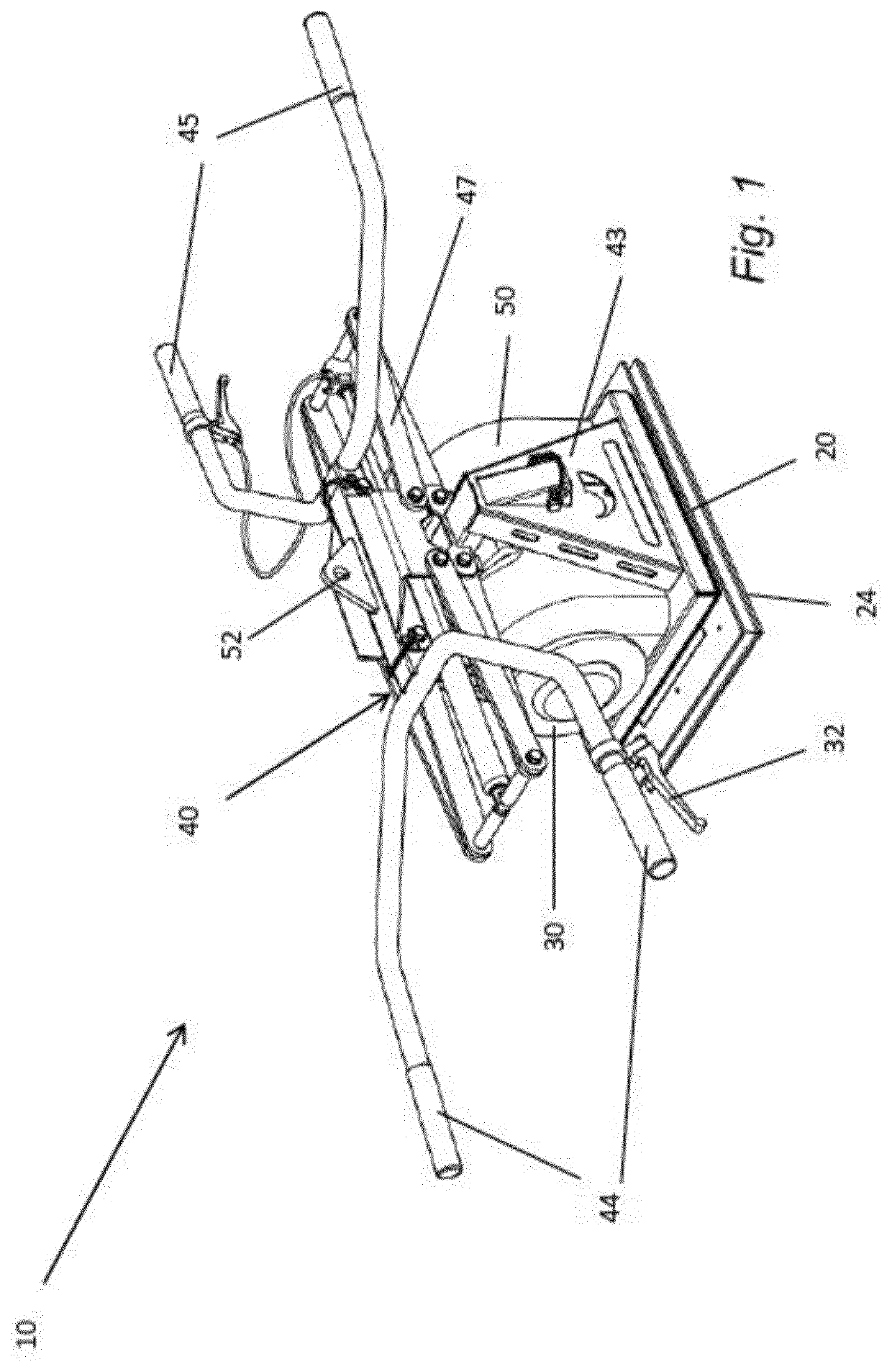
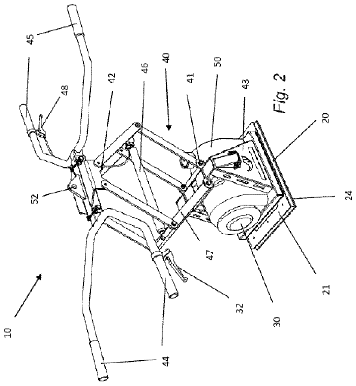
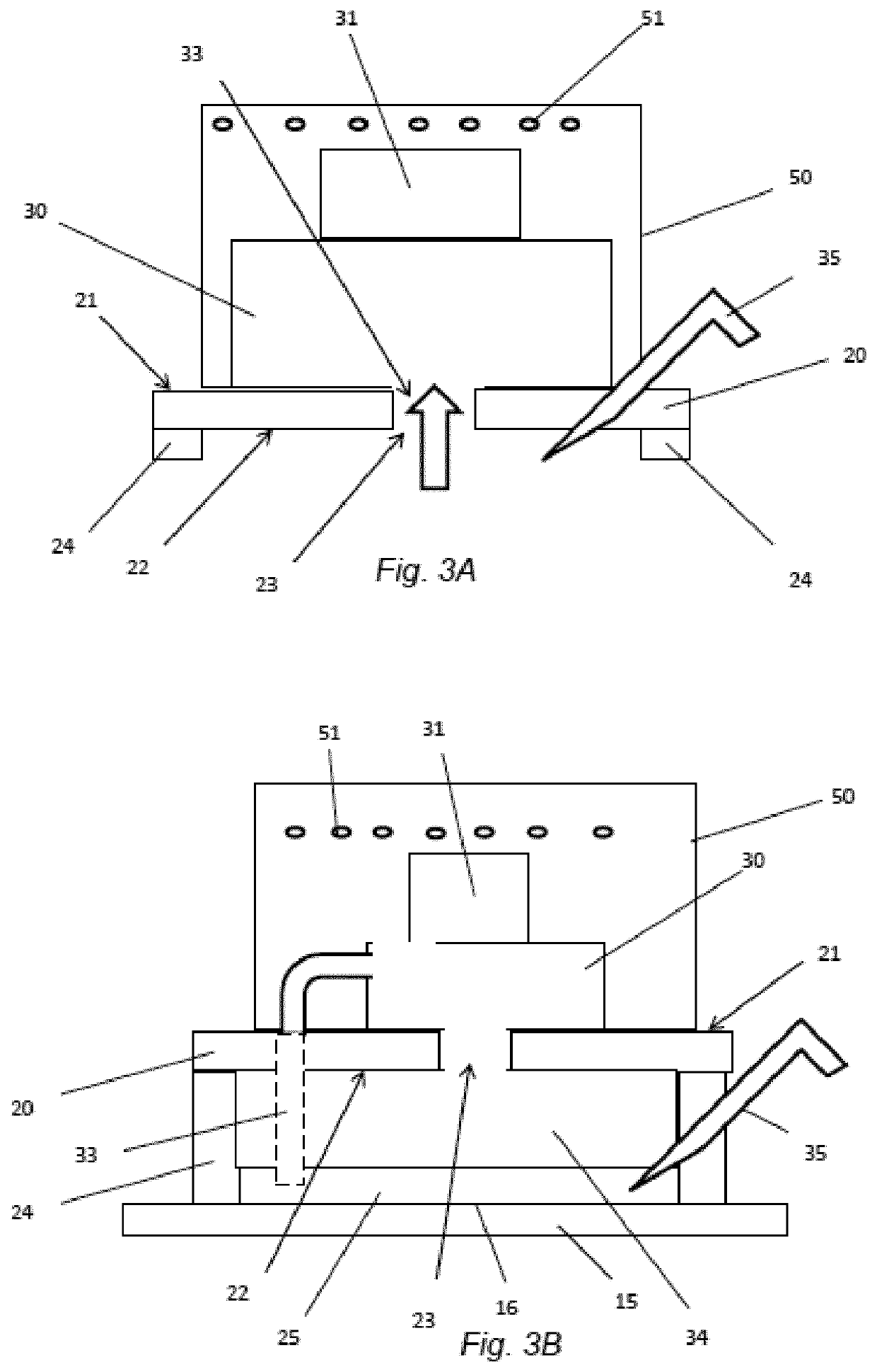
[0037]It is to be understood that the drawings are schematic and that individual components are not necessarily drawn to scale. The manual vacuum lifting device shown in the figures is provided as examples only and should not be considered limiting to the invention as disclosed herein. In particular, it should be understood that the vacuum lifting device as disclosed herein may be applied to any technical field where a manual vacuum lifting device is applicable. Furthermore, the size and shape of the manual vacuum lifting device may be different from what is shown in the figures. The vacuum lifting device may have a different sizes and shapes, and may have a differently shaped handles, bases, vacuum generating members, actuators or reservoirs as set out herein.

[0038]FIGS. 1 to 3 disclose a manual vacuum lifting device 10 that may be used for lifting and / or repositioning of an article 15 having an external surface. The vacuum lifting device 10 as disclosed herein is configured to lif...


PUM


Abstract

A vacuum lifting device to facilitate the lifting and / or repositioning of an article having an external surface as set out herein comprises at least one pair of handles and a base having opposed first and second surfaces, the base having an aperture arranged through the base. The second surface is arranged is provided with a continuous sealing joint projecting downwards from the second surface defining an enclosed area which includes the aperture on the bottom surface of the base. The vacuum lifting device also comprises a suction conduit arranged to be connected to a vacuum generating member and configured to be in fluid connection with the second surface of the base through the aperture. The vacuum lifting device further comprises an extendable lifting member arranged between the at least one pair of handles and the first surface of the base, the lifting member is actuated by a lift actuating member for shifting the base in a vertical direction transferring said vacuum lifting device (10) between an extended and a compressed state. A method for using the vacuum lifting device is also disclosed.

Description

TECHNICAL FIELD[0001]The present disclosure relates to vacuum lifting devices, and more particularly to manual vacuum lifting devices for lifting, moving and positioning heavy planar objects. A method for manual displacement of such heavy planar objects using the manual vacuum lifting device is also described.BACKGROUND OF THE INVENTION[0002]In the construction trade the use of slabs of construction material such as concrete slabs, paving stones or the like are common. These slabs are generally quite large (90 cm×60 cm×5 cm) and heavy (sometimes about as much as 90 kg) thus making manual lifting, moving and positioning these slabs very difficult. This is particularly the case where slabs are placed on a flat surface e.g. the ground or the back of a lorry where it is very difficult to get a good grip of the slab.[0003]It can for example be very difficult when a patio or path or the like is being constructed, to move and / or lay the slabs into position, since spaces where the slabs are...

Claims


Application Information

Patent Timeline
IPC IPC(8): B65G7/12B25J15/06B66F7/06B66C1/02
CPCB65G7/12B25J15/0625B25J15/0683B66F7/065B66C1/0225B65G2201/022B65G2201/0223E01C19/524B65G47/91E01C19/526B25J13/02B66C1/02
Inventor ANDERSSON, ROLAND
Owner PRITEC VACULYFT AB
Learn More