[0011]Hereinafter, an embodiment of a preparative liquid chromatograph and an analysis method according to the present invention will be described with reference to the drawings.
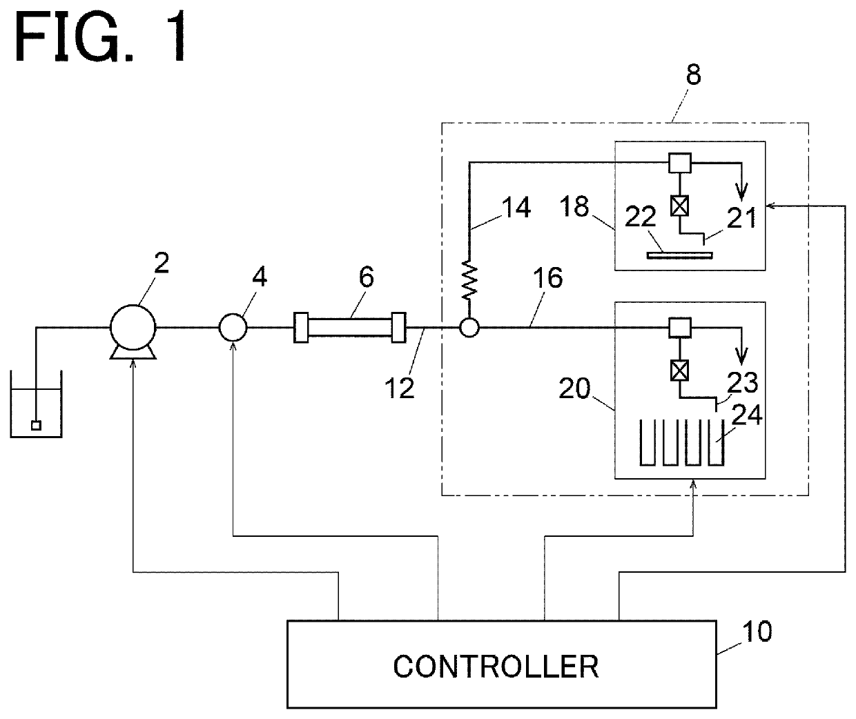
[0012]As shown in FIG. 1, the preparative liquid chromatograph of this embodiment includes a liquid feeding pump 2, an injector 4, a separation column 6, an eluate fractionator 8, and a controller 10.
[0013]The liquid feeding pump 2 feeds a mobile phase. The injector 4 is provided downstream of the liquid feeding pump 2 and injects a sample into the mobile phase fed by the liquid feeding pump 2. The separation column 6 is provided downstream of the injector 4, and components in the sample injected into the mobile phase by the injector 4 are separated from each other in the separation column 6.
[0014]The eluate fractionator 8 is provided downstream of the separation column 6. The eluate fractionator 8 includes a first channel 14 and a second channel 16 branched from each other from a channel 12 on the outlet side of the separation column 6 and divides the flow of the eluate from the separation column 6 into a “flow of a minute flow rate” flowing through the first channel 14 and an “other flow” flowing through the second channel 16. The split ratio between the first channel 14 and the second channel 16 is, for example, 10 times or more, and the flow rate of the eluate flowing through the first channel 14 is, for example, 10 μL/min or less. The first channel 14 communicates with a first fractionator 18, and the second channel 16 communicates with a second fractionator 20.
[0015]The first fractionator 18 is configured to drop the eluate forming the “flow of a minute flow rate” in the first channel 14 from the tip of a nozzle 21 and extract the eluate into a plate 22 which is an fractionation container. A plurality of wells (eluate holding parts) are provided on the upper surface of the plate 22. Although not shown, the first fractionator 18 includes a mechanism for moving the nozzle 21 and/or the plate 22 in a planar manner and drops the eluate from the separation column 6 from the nozzle 21 to a predetermined well of the plate 22.
[0016]The second fractionator 20 is configured to drop the eluate forming the “other flow” in the second channel 16 from the tip of a nozzle 23 and extract the eluate into a collection container 24. A plurality of collection containers 24 are arrayed in a planar manner in the second fractionator 20, and the eluate from the separation column 6 is dropped from the nozzle 23 to a predetermined collection container 24.
[0017]The controller 10 controls the operations of the liquid feeding pump 2, the injector 4, and the eluate fractionator 8. The controller 10 can be realized by a computer device including a central processing unit (CPU), a storage memory, and the like. A target portion to be extracted in the eluate from the separation column 6 can be set in advance by a user to the controller 10. The number of the target portion to be extracted may be plural.
[0018]The controller 10 is configured to control the operations of the first fractionator 18 and the second fractionator 20 such that the target portion set by the user is extracted into each of the plate 22 of the first fractionator 18 and the collection container 24 of the second fractionator 20. When the user sets a plurality of target portions, eluates each corresponding to each of a plurality of fractions extracted into the plurality of wells of the plate 22 of the first fractionator 18 (eluate containing the same component as the corresponding fraction) are collected in individual collection containers 24 of the second fractionator 20 different from each other. Although not shown in FIG. 1, a detector for detecting the sample separated by the separation column 6 may be provided on the channel 12 downstream of the separation column 6.
[0019]In such a case, the controller 10 can control the operations of the first fractionator 18 and the second fractionator 20 based on a detection signal obtained by the detector provided on the channel 12. As the detector for detecting the separated sample, a PDA detector, a fluorescence detector, or the like is used.
[0020]The controller 10 is configured to store a correspondence relationship between the target portion extracted into the plate 22 in the first fractionator 18 and the target portion extracted into the collection container 24 in the second fractionator 20, that is, a correspondence relationship between the position of the well and the position of the collection container 24 where the same target portion is extracted in a predetermined storage region. The component contained in the target portion extracted into each well of the plate 22 is subjected to a drying and solidifying treatment for removing the solvent, and then supplied to a detector using vibrational spectroscopy such as a Raman spectrometer to be detected. The target portion collected in the collection container 24 is used when the component detected by the detector using vibrational spectroscopy needs to be further analyzed.
[0021]An example of an analysis method using the above-described preparative liquid chromatograph will be described with reference to FIG. 1 and the flowchart of FIG. 2.
[0022]The injector 4 injects a sample to be analyzed into a mobile phase (step 101). The sample injected into the mobile phase is guided to the separation column 6, and components in the sample are separated from each other (step 102). The eluate from the separation column 6 is divided into the first channel 14 and the second channel 16 at the downstream of the separation column 6, and a flow of the eluate of a minute flow rate is formed in the first channel 14 (step 103). A preset target portion of the eluate forming the flow of a minute flow rate in the first channel 14 is extracted into the plate 22 in the first fractionator 18 (step 104).
[0023]After the target portion of the eluate from the separation column 6 is extracted into the plate 22, the plate 22 is heated or the like to dry and solidify the component contained in the target portion (step 105), and the component is detected by a detector such as a Raman spectrometer (step 106).
[0024]The example described above is merely an example of the embodiment of the preparative liquid chromatograph and the analysis method according to the present invention. The embodiment of a preparative liquid chromatograph according to the present invention is as follows.
[0025]An embodiment of the preparative liquid chromatograph according to the present invention includes a liquid feeding pump that feeds a mobile phase, an injector that injects a sample into the mobile phase at a downstream of the liquid feeding pump, a separation column for separating components in the sample injected into the mobile phase by the injector at a downstream of the injector, and an eluate fractionator configured to divide a flow of the eluate from the separation column into a flow of a minute flow rate and another flow at a downstream of the separation column and to extract at least a part of an eluate that forms the flow of a minute flow rate into an fractionation container.
[0026]In a specific aspect of the embodiment, the eluate fractionator has a first channel and a second channel that are branched from each other at the downstream of the separation column, the eluate that forms the flow of a minute flow rate flows through the first channel, an eluate that forms the other flow flows through the second channel, and the eluate that has passed through the first channel is extracted by being dropped to the fractionation container.
[0027]In the specific aspect, the eluate fractionator may be configured to collect the eluate that has passed through the second channel in a collection container. Such a form enables the eluate collected in the collection container to be used for reanalysis or the like of the component extracted into the fractionation container and detected by a Raman spectrometer or the like.
[0028]In the above case, the preparative liquid chromatograph may include a controller configured to extract a plurality of portions of the eluate that has passed through the first channel into the fractionation container by controlling an operation of the eluate fractionator and to separately collect portions each corresponding to each of the plurality of portions extracted into the fractionation container in the eluate that has passed through the second channel into the collection container different from each other.
[0029]In the above case, a plurality of eluate holding parts for holding the eluate dropped from the eluate fractionator are arrayed in a planar manner in the fractionation container, and the controller is configured to store a correspondence relationship between each of the eluate holding parts in which each of the plurality of portions extracted in the fractionation container is held and each collection container in which each portion corresponding to each of the plurality of portions in the eluate that has passed through the second channel is collected.
[0030]An embodiment of the analysis method according to the present invention includes an injection step of injecting a sample into a mobile phase that flows at a predetermined flow rate, a separation step of separating components in the sample injected into the mobile phase in the injection step from each other using a separation column, a flow dividing step of dividing a flow of an eluate from the separation column into a flow of a minute flow rate and another flow, an extraction step of extracting at least a part of the eluate that forms the flow of a minute flow rate divided in the dividing step into an fractionation container, a drying/solidifying step of drying the eluate extracted into the fractionation container in the extraction step to dry and solidify a component in the eluate, and a detection step of detecting the component dried and solidified in the drying/solidifying step.
DESCRIPTION OF REFERENCE SIGNS
[0031] 2: liquid feeding pump [0032] 4: injector [0033] 6: separation column [0034] 8: eluate fractionator [0035] 10: controller [0036] 12: channel at downstream of separation column [0037] 14: first channel [0038] 16: second channel [0039] 18: first fractionator [0040] 20: second fractionator [0041] 21, 23: nozzle [0042] 22: fractionation container [0043] 24: collection container