Axially aligned rotationally adjustable flow control valve

a technology of rotationally adjustable and flow control valve, which is applied in the direction of fluid pressure control, process and machine control, instruments, etc., to achieve the effect of reducing friction moments and increasing cv values

Active Publication Date: 2015-10-08
GRISWOLD CONTROLS LLC
View PDF0 Cites 2 Cited by
  • Summary
  • Abstract
  • Description
  • Claims
  • Application Information

AI Technical Summary

Benefits of technology

[0017]The valve has two control disks, one stationary and one that is movable and it is the interface between openings on both disks that allow the user to select a particular flow rate. Due to the smoothness of the disks, which are preferably made of ceramic materials, the friction moment is greatly reduced even under high pressure fluid flow.
[0018]As an embodiment the user can incorporate an adjustable Cv control disk into the valve so that the maximum Cv or maximum flow rate can be established for the valve. This allows the user to set the flow rate and also allows the system to be able to anticipate the maximum flow coming out of the valve.
[0019]Another embodiment is the addition of a larger Cv control surface which will enable the valve to rotate through up to a total of 300° of rotational movement. This allows a user to more finitely adjust the valve over a larger rotational range and can accommodate higher Cv values. The 300° degrees of rotation is not a limiting factor this invention, but rather a range of motion that will be most suitable for the application in HVAC piping structures.

Problems solved by technology

Since this valve design does not permit increases in cavitation or turbulent flow in the piping system, it is possible to measure the pressure differential at a location that is very close to the actual adjustment means, which is one of the drawbacks with normal ball valves.

Method used


Image

  • Axially aligned rotationally adjustable flow control valve
  • Axially aligned rotationally adjustable flow control valve
  • Axially aligned rotationally adjustable flow control valve

Examples


Embodiment Construction

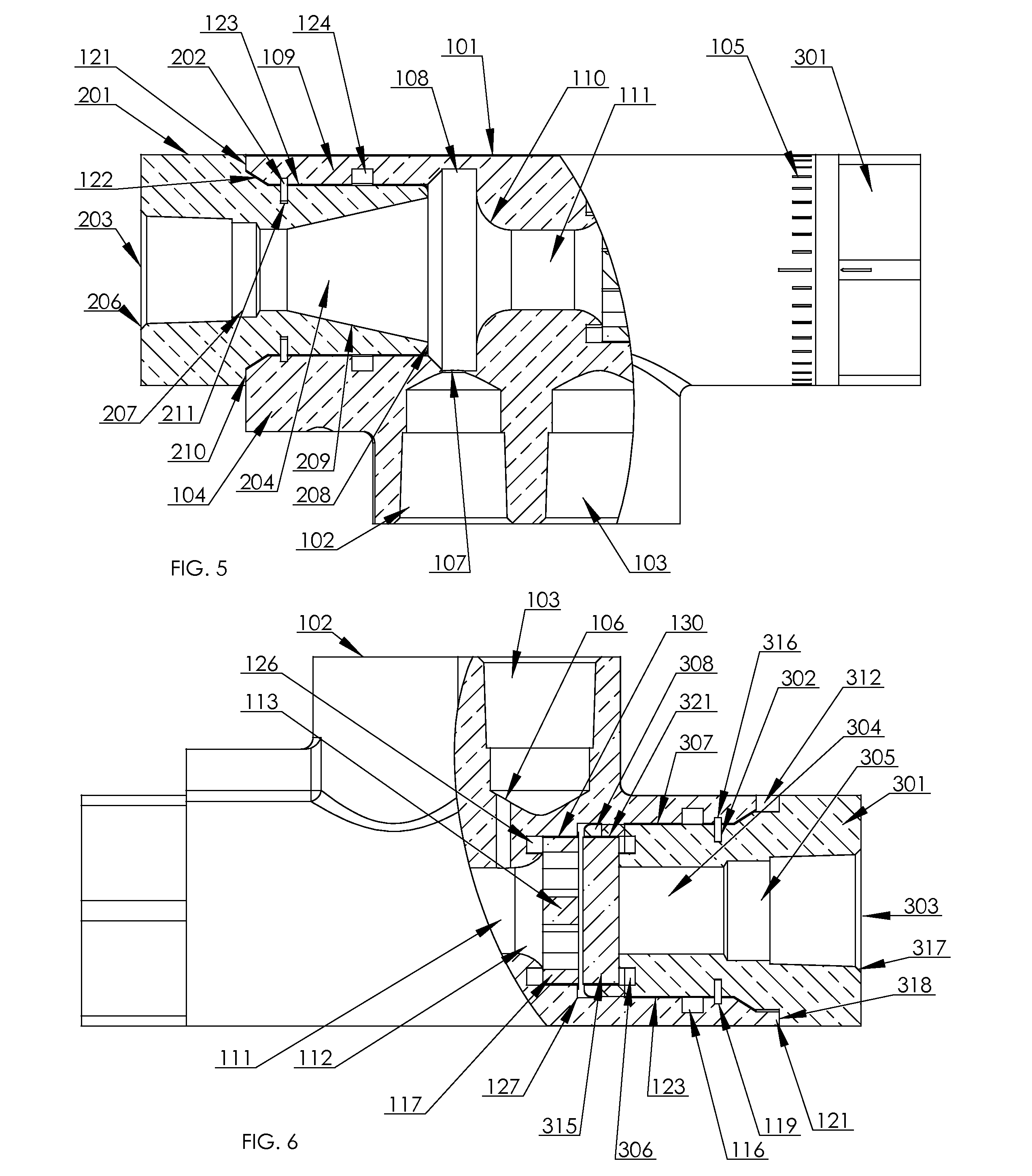
[0036]This invention as disclosed in the drawings has the principle use in the HVAC environment but there exists no limiting language to prevent this invention to be practiced in other fields of use. The invention consists of three main elements, inlet section, a body and an outlet portion. This invention is an adjustable valve that is adjusted axially to the flow of the fluid, with the further embodiments of ports that are designed to report differential pressure through the valve and whereby the Cv of the valve can be set and still have the valve go to complete shutoff.

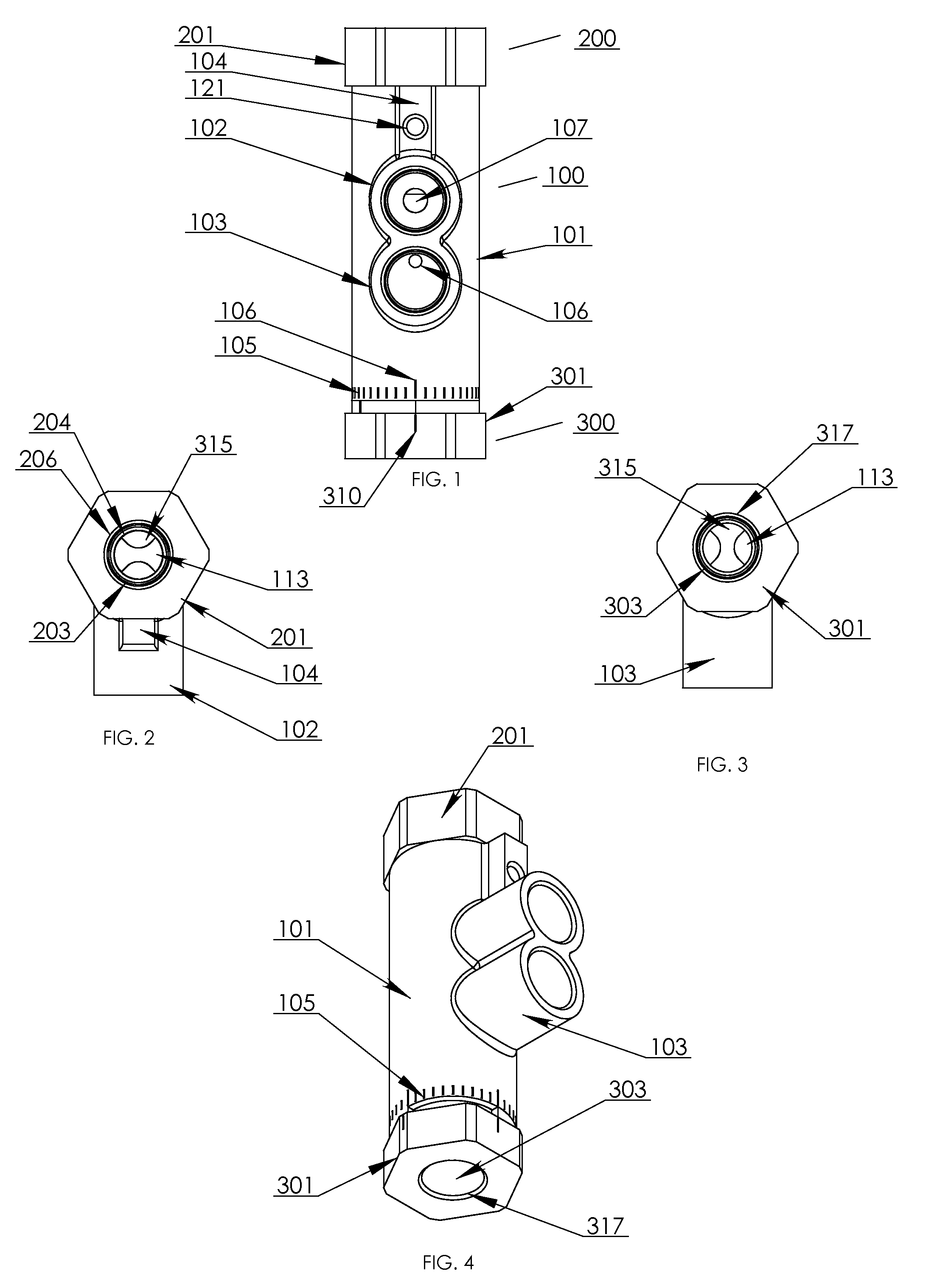
[0037]In FIG. 1, the valve is shown with its three main sections; a central body 100, an inlet portion 200 and an outlet portion 300. Shown in this view are differential pressure measurement means, shown as ports 102 for high side pressure and port 103 for low side pressure. It is disclosed that this invention will function without ports 102 and 103 as the measurement of differential pressure across this valve can b...


PUM


Abstract

A rotationally adjustable valve is disclosed whereby the user is able to control the flow of fluids from complete shutoff to maximum flow by rotating the body of the valve, said rotation being axial to the flow of the fluid. Additionally, the user is able to attach high and low pressure test probes directly to the valve, as it is rotatably adjusted, so that additional equipment is not required next to the valve. An embodiment of this invention includes the use of an adjustable Cv disk to set the maximum flow of the valve, rather than just create a simple 180° on / off, very similar to a current 90° ball valve that this device will replace. All of the problems associated with the ball valve have been minimized including creating a linear relationship between the percentage open of the valve and the percentage of maximum flow of the valve.

Description

CROSS-REFERENCE TO RELATED APPLICATIONS[0001]There are not any pending applications that cross-reference this application.FIELD OF THE INVENTION[0002]The field of this invention is the heating ventilation and cooling (HVAC) industry where fluids are the medium for the heating and cooling. Fluids that are sent from boilers or chillers are routed through piping structures which need to be balanced in terms of pressure and flow in order to even distribute the hot or cold fluids into air handler units which deliver temperature controlled air. In this industry, quarter-turn ball valves are usually used which present a host of problems and restrictions on their location and use.BACKGROUND OF THE INVENTION[0003]This device is used in piping system in large HVAC systems where the control of the amount of flow is desired. Currently, most controls that regulate the flow in piping systems are based on the principle shown in the quarter-turn ball valve, where the operator can have complete shut...

Claims


Application Information

Patent Timeline
Patent Type & Authority Applications(United States)
IPC IPC(8): F16K3/32F16K31/44F16K3/02
CPCF16K3/32F16K3/0209Y10T137/87917F16K31/44F16K3/029F16K3/085G01F1/40G01F1/44G01F15/005Y10T137/776G05D7/0635
Inventor TUINEAG, STEFANHOLLOWAY, BRYAN
Owner GRISWOLD CONTROLS LLC
Why Eureka
Try Eureka