Object detection apparatus, object detection method,and non-transitory computer readable medium

a technology of object detection and object detection, applied in the field of object detection apparatus, an object detection method, and a program, can solve the problems of difficult precise estimation of the permittivity of a substance, increase in cost due to use of a camera, measurement error of a permittivity, etc., and achieve the effect of suppressing cost increase and increasing measurement precision

Pending Publication Date: 2022-09-22
NEC CORP
View PDF0 Cites 0 Cited by
  • Summary
  • Abstract
  • Description
  • Claims
  • Application Information

AI Technical Summary

Benefits of technology

[0011]In Patent Document 3, a three-dimensional microwave image is generated by an antenna array configured with a plurality of transmission antennas and a plurality of reception antennas. Unlike the methods of using a single transmission antenna and a single reception antenna in Patent Document 2 and Non-Patent Document 1, use of an antenna array is less susceptible to noise of a radar apparatus.
[0013]An object of the present invention is to increase measurement precision while suppressing cost increase when the permittivity of an object is measured by using a radio wave.
[0017]The present invention can increase measurement precision while suppressing cost increase when the permittivity of an object is measured by using a radio wave.

Problems solved by technology

Use of a single transmission antenna and a single reception antenna has a problem that the method is susceptible to noise of a radar apparatus and precise estimation of the permittivity of a substance is difficult.
Therefore, there is a problem of cost increase due to use of a camera.
There is a problem that synchronization deviation between the radar and the camera causes a measurement error of a permittivity when a measurement target object moves.

Method used


Image

  • Object detection apparatus, object detection method,and non-transitory computer readable medium
  • Object detection apparatus, object detection method,and non-transitory computer readable medium
  • Object detection apparatus, object detection method,and non-transitory computer readable medium

Examples


first example embodiment

Apparatus Configuration

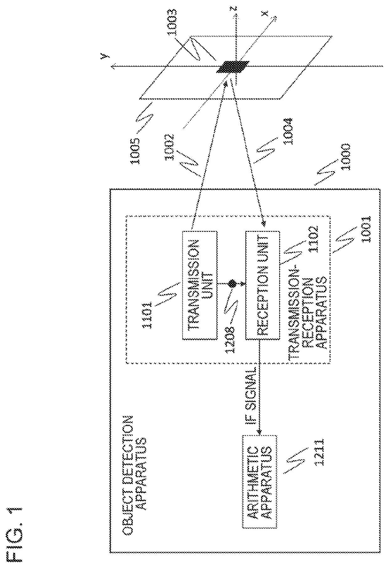
[0034]First, a configuration of an object detection apparatus according to a first example embodiment is described by using FIG. 1. An object detection apparatus 1000 according to the present example embodiment illustrated in FIG. 1 is an apparatus for detecting an object by a radio wave. As illustrated in FIG. 1, the object detection apparatus 1000 includes a transmission unit 1101, a reception unit 1102, and an arithmetic apparatus 1211.

[0035]Next, FIG. 2 illustrates internal configurations of the transmission unit 1101 and the reception unit 1102 according to the present example embodiment. In the example illustrated in FIG. 2, the transmission unit 1101 includes an oscillator 1201, a variable amplitude phase shifter 1207, and a transmission antenna 1202. The reception unit 1102 includes a reception antenna 1203, a mixer 1204, and an interface circuit 1205. Furthermore, as also illustrated in FIG. 1, the transmission unit 1101 and the reception unit 1102 ar...

second example embodiment

[0062]Next, a second example embodiment is described. The second example embodiment provides an object detection method in a case of a surface of a target object 1003 not being parallel to an aperture plane 1400 formed by a transmission antenna 1202 and a reception antenna 1203 in an object detection apparatus 1000, as illustrated in FIG. 7.

Apparatus Configuration

[0063]An apparatus configuration according to the second example embodiment is illustrated in FIG. 1, FIG. 2, and FIG. 6. FIG. 1 and FIG. 2 are in common with the first example embodiment, and therefore duplicated description thereof is omitted.

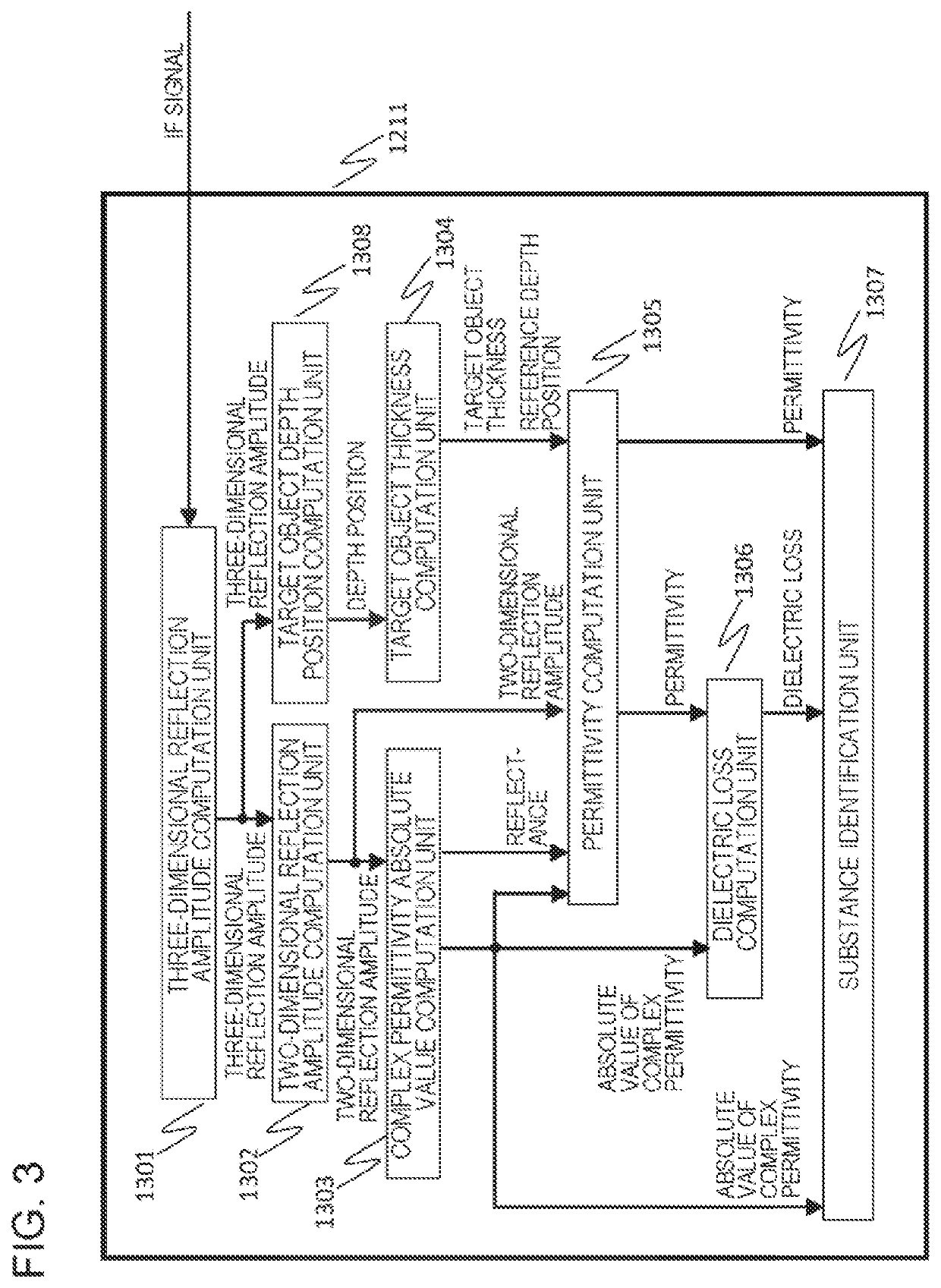
[0064]FIG. 6 illustrates an internal configuration of an arithmetic apparatus 1211 according to the second example embodiment. The internal configuration of the arithmetic apparatus 1211 according to the second example embodiment illustrated in FIG. 6 is acquired by adding a target object orientation computation unit 1309 to the internal configuration of the arithmetic apparatus 1211...


PUM


Abstract

For increasing measurement precision while suppressing cost increase when measuring a permittivity of an object using a radio wave, an object detection apparatus includes a transmission unit projecting a radio wave toward a target object by using a transmission antenna, a reception unit receiving the radio wave reflected by the target object by a reception antenna and generating an intermediate frequency signal, and an arithmetic apparatus. The arithmetic apparatus computes a reflection amplitude of the target object from the intermediate frequency signal, computes a reflectance from the reflection amplitude, computes a complex permittivity absolute value of the target object from the computed reflectance, computes a depth position of the target object from the reflection amplitude, computes a thickness of the target object from the depth and the reflection amplitude, and computes a permittivity of the target object from the reflection amplitude, the complex permittivity absolute value, and the thickness.

Description

[0001]This application is based on Japanese patent application No. 2021-047049, the content of which is incorporated hereinto by reference.BACKGROUNDTechnical Field[0002]The present invention relates to an object detection apparatus, an object detection method, and a program for projecting a radio wave onto a detection target object and recognizing or identifying existence of the detection target object by using the radio wave reflected from the target object.Related Art[0003]Unlike light, a radio wave (such as a microwave, a millimeter wave, or a terahertz wave) has an excellent ability to penetrate an object. United States Patent Application Publication No. 2014 / 0167784 (Patent Document 1) proposes an apparatus projecting a radio wave penetrating clothing and a bag onto a hidden article under clothing or in a bag from a radar apparatus, receiving the radio wave reflected by the article by the radar apparatus, and imaging and inspecting the article, based on the received radio wave...

Claims


Application Information

Patent Timeline
Patent Type & Authority Applications(United States)
IPC IPC(8): G01S7/41G01S13/88
CPCG01S7/412G01S13/887G01S7/411G01S2013/0263G01S13/0218G01S13/34G01S13/44G01S13/89
Inventor YAMANOUCHI, SHINGONOMURA, TOSHIYUKIARLYOSHI, MASAYUKIOGURA, KAZUMINESUMIYA, TATSUYA
Owner NEC CORP
Why Eureka
Try Eureka