
Water electrolysis system and method of operating same

a water electrolysis and system technology, applied in the field of water electrolysis systems, can solve the problems of complex and uneconomical zone structure, and achieve the effect of simple and economical

Active Publication Date: 2013-01-29
HONDA MOTOR CO LTD
View PDF3 Cites 2 Cited by
  • Summary
  • Abstract
  • Description
  • Claims
  • Application Information

AI Technical Summary

Benefits of technology

[0012]It is an object of the present invention to provide a water electrolysis system which is simple and economical and which is capable of accommodating various electronic components in an appropriate environment.
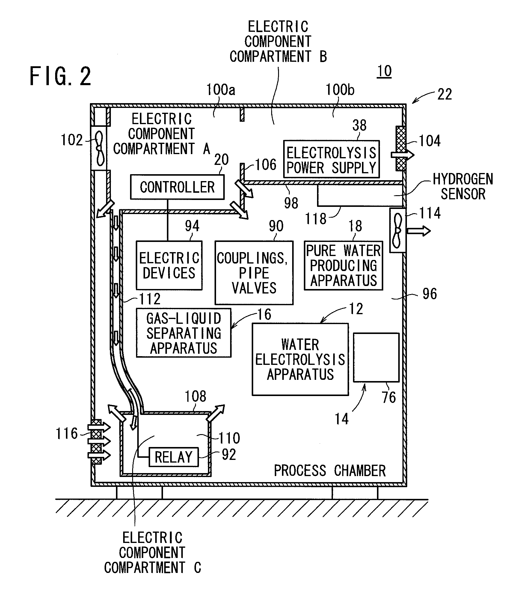
[0017]The first electric component compartment may be divided into two first electric component compartments. One of the first electric component compartments may house therein electronic components which produce a relatively small amount of heat and are susceptible to heat and noise, and the other first electric component compartment may house therein electronic components which produce a relatively large amount of heat and a low level of noise.
[0024]The first electric components and the second electric components which have different characteristics are not placed in one compartment, but housed in different compartments. Therefore, the first electric components and the second electric components do not adversely affect each other. The second electric component compartment is free of any air blowers such as a fan. The number of fans that are required to maintain a positive pressure in the water electrolysis system is thus effectively reduced, making the water electrolysis system simple and economical and making it possible to accommodate various electronic components in an appropriate environment.
[0025]The electric component compartment is initially kept under a positive pressure, and then the accommodating chamber is kept under a negative pressure while being ventilated, after which the water electrolysis apparatus is operated. Even if hydrogen leaks from the water electrolysis apparatus into the accommodating chamber, it is reliably prevented from entering into the electric component compartment. Therefore, the electric component compartment is not required to be highly hermetically sealed with respect to the accommodating chamber. The water electrolysis system is thus simple in structure and economical to manufacture.

Problems solved by technology

The electric components housed in the zone A include electric components which are susceptible to noise and electric components which tend to generate high-level noise.
However, such a zone structure is complex and uneconomical.

Method used


Image

  • Water electrolysis system and method of operating same
  • Water electrolysis system and method of operating same
  • Water electrolysis system and method of operating same

Examples


first embodiment

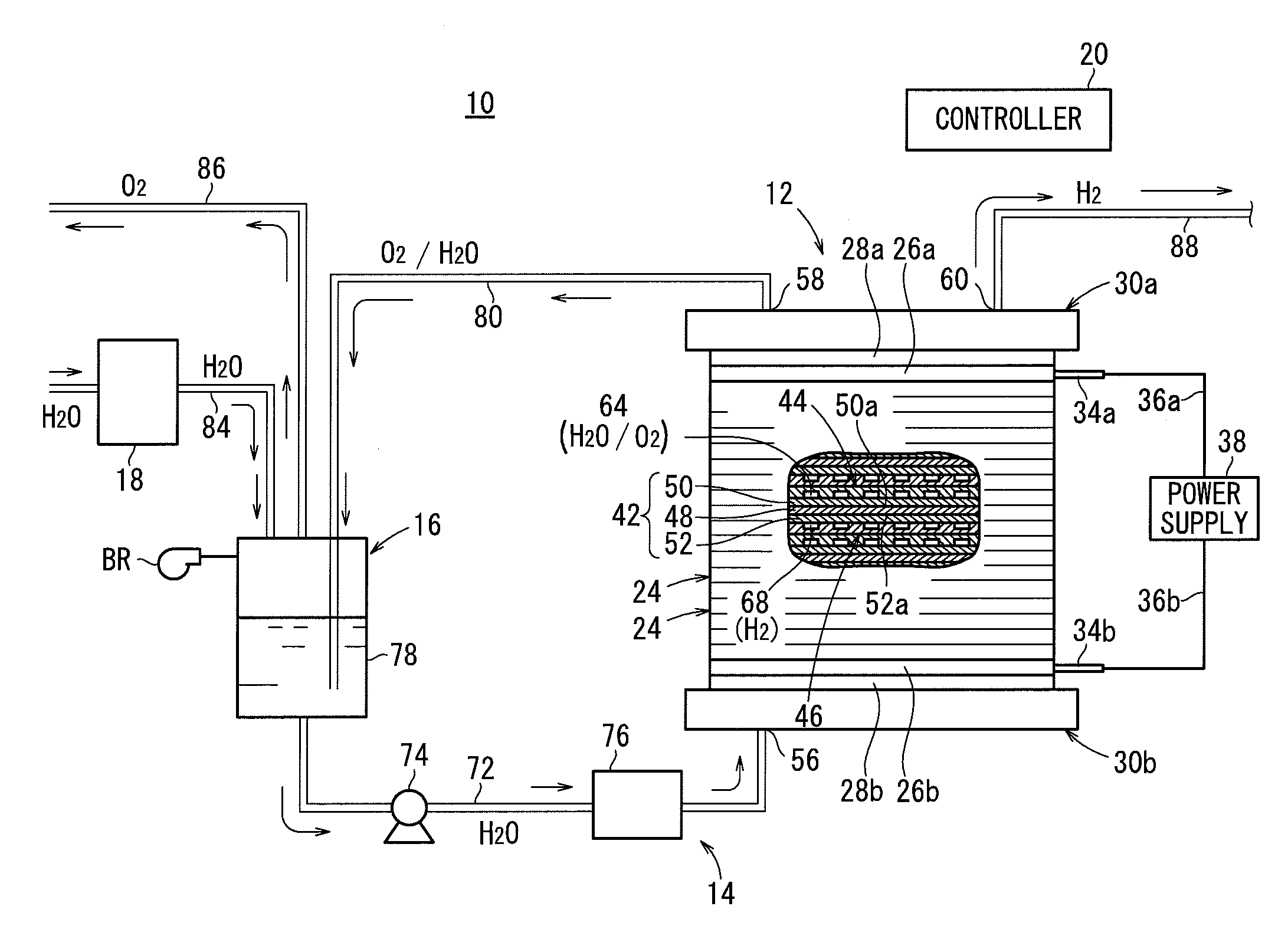
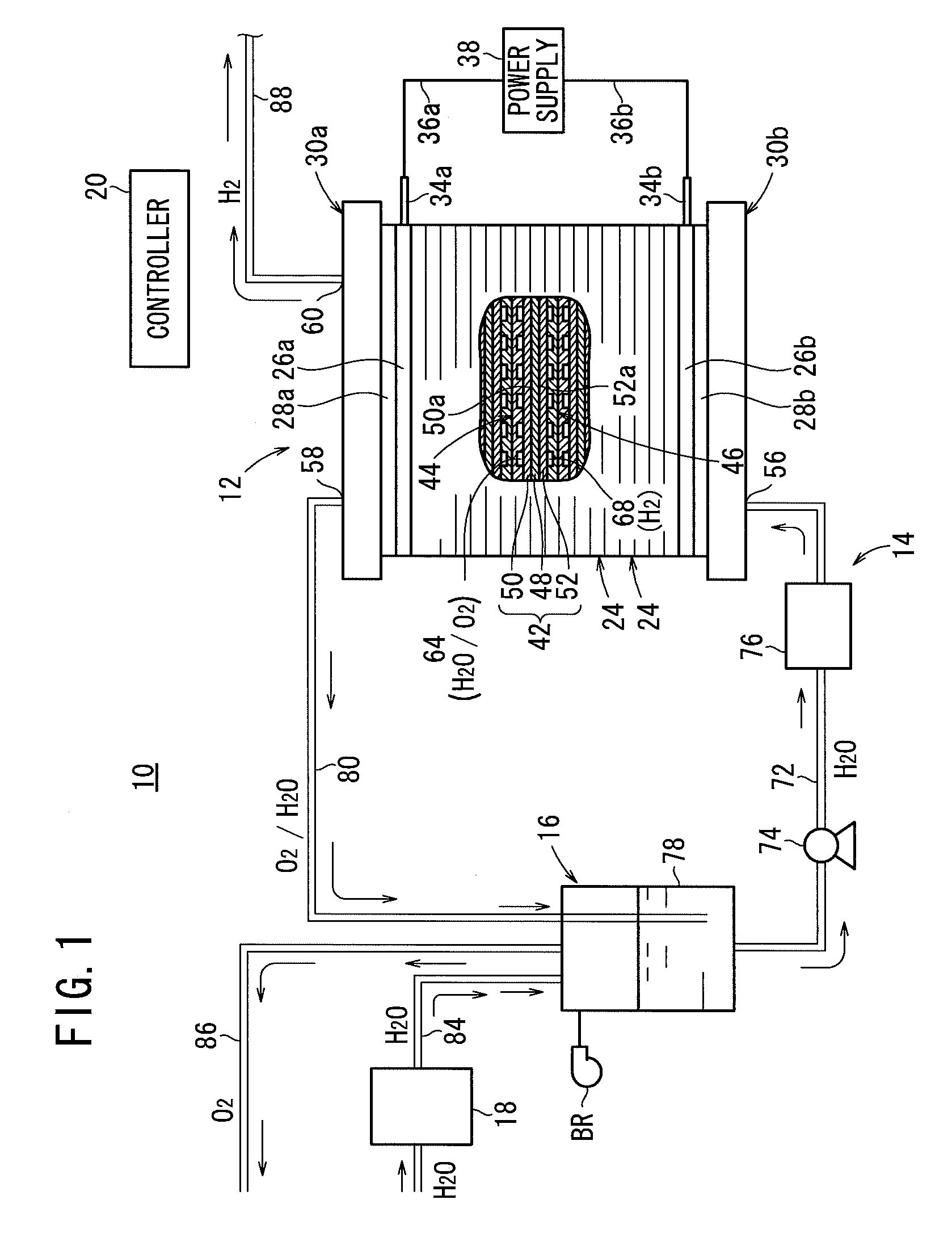
[0035]As shown in FIGS. 1 and 2, a water electrolysis system 10 according to the present invention includes a water electrolysis apparatus 12 for electrolyzing water (pure water) to produce oxygen and high-pressure hydrogen (hydrogen under a pressure higher than the normal pressure), a water circulating apparatus 14 for circulating the water to the water electrolysis apparatus 12, a gas-liquid separating apparatus 16 for separating the oxygen and hydrogen (gas) discharged from the water electrolysis apparatus 12 from the water in the water circulating apparatus 14 and storing the water, and a pure water producing apparatus 18 for supplying pure water produced from tap water to the gas-liquid separating apparatus 16, and a controller 20. The water electrolysis apparatus 12, the water circulating apparatus 14, the gas-liquid separating apparatus 16, the pure water producing apparatus 18, and the controller 20 are accommodated in a casing 22.

[0036]As shown in FIG. 1, the water electrol...

second embodiment

[0080] the water electrolysis system 130 is simple and economical and capable of accommodating various electronic components in an appropriate environment. As the first electric component compartments 100a, 100b and the second electric component compartment 110 are not required to be highly hermetically sealed, the water electrolysis system 130 is simple in structure and economical to manufacture.


PUM

PropertyMeasurementUnit
porosityaaaaaaaaaa
porosityaaaaaaaaaa
pressureaaaaaaaaaa

Abstract

A water electrolysis system includes a water electrolysis apparatus for producing high-pressure hydrogen by electrolyzing pure water and a casing. The casing defines therein an accommodating chamber accommodating the water electrolysis apparatus etc. therein, first electric component compartments separate from the accommodating chamber and housing a controller and an electrolysis power supply therein, the first electric component compartments having first fans for introducing external air, and a second electric component compartment separate from the accommodating chamber and housing a relay, the second electric component compartment being connected to the first electric component compartments by a pipe.

Description

CROSS-REFERENCE TO RELATED APPLICATION[0001]This application is based upon and claims the benefit of priority from Japanese Patent Applications No. 2010-079329 filed on Mar. 30, 2010 and No. 2010-272265 filed on Dec. 7, 2010, of which the contents are incorporated herein by reference.BACKGROUND OF THE INVENTION[0002]1. Field of the Invention[0003]The present invention relates to a water electrolysis system having a water electrolysis apparatus which includes an electrolyte membrane and current collectors disposed on respective opposite sides of the electrolyte membrane, providing anodes and cathodes, wherein the water electrolysis apparatus electrolyzes water to generate oxygen on the anodes and hydrogen on the cathodes, and a casing which has a chamber accommodating the water electrolysis apparatus therein, and a method of operating such a water electrolysis system.[0004]2. Description of the Related Art[0005]Solid polymer electrolyte fuel cells generate DC electric energy when ano...

Claims


Application Information

Patent Timeline
Patent Type & Authority Patents(United States)
IPC IPC(8): C02F1/461
CPCC25B1/04C25B9/00C25B15/08Y02E60/366Y02E60/36
Inventor YOSHIDA, NOBUYOSHINAKAZAWA, KOJIOKABE, MASANORITAKEUCHI, JUN
Owner HONDA MOTOR CO LTD
Learn More