Supercharge Your Innovation With Domain-Expert AI Agents!

Prm-accessible aircraft lavatory

a technology for aircraft lavatory and access, which is applied in the direction of toilet fittings, aircraft crew accommodation, transportation and packaging, etc., can solve the problems of inconvenient use of lavatory units, inconvenient access to toilets in lavatory units,

Pending Publication Date: 2022-09-29
ST ENG AEROSPACE LTD
View PDF0 Cites 1 Cited by
  • Summary
  • Abstract
  • Description
  • Claims
  • Application Information

AI Technical Summary

Benefits of technology

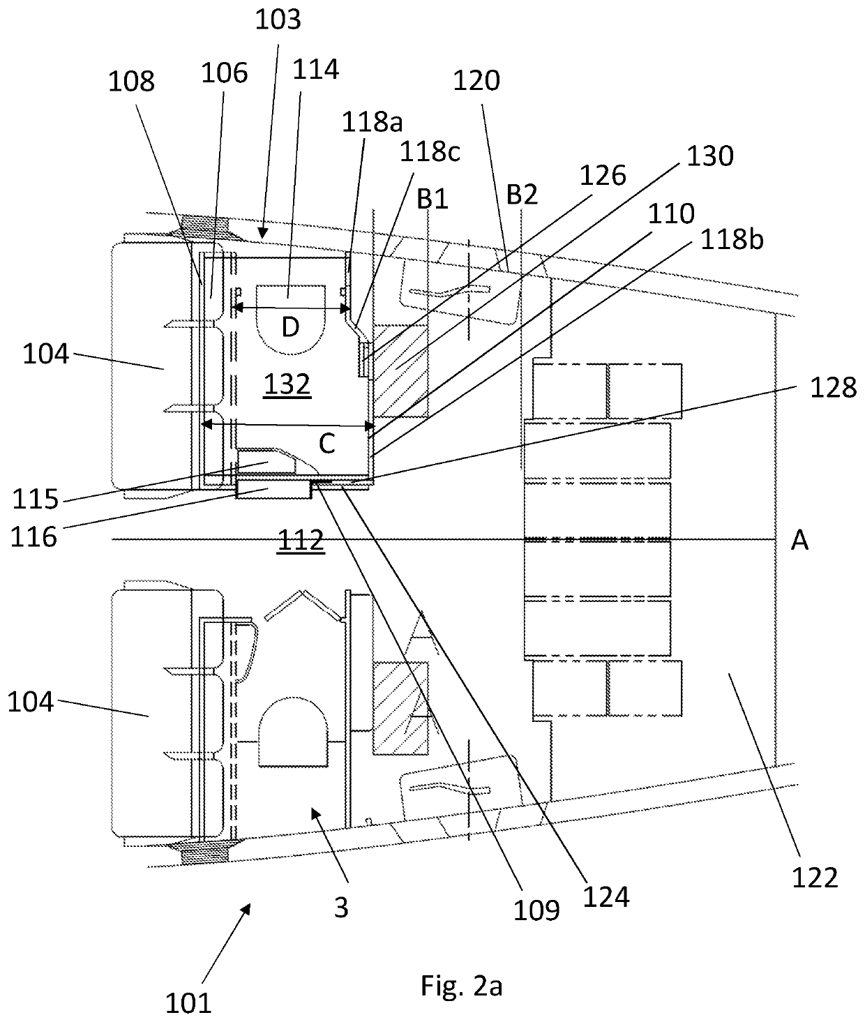
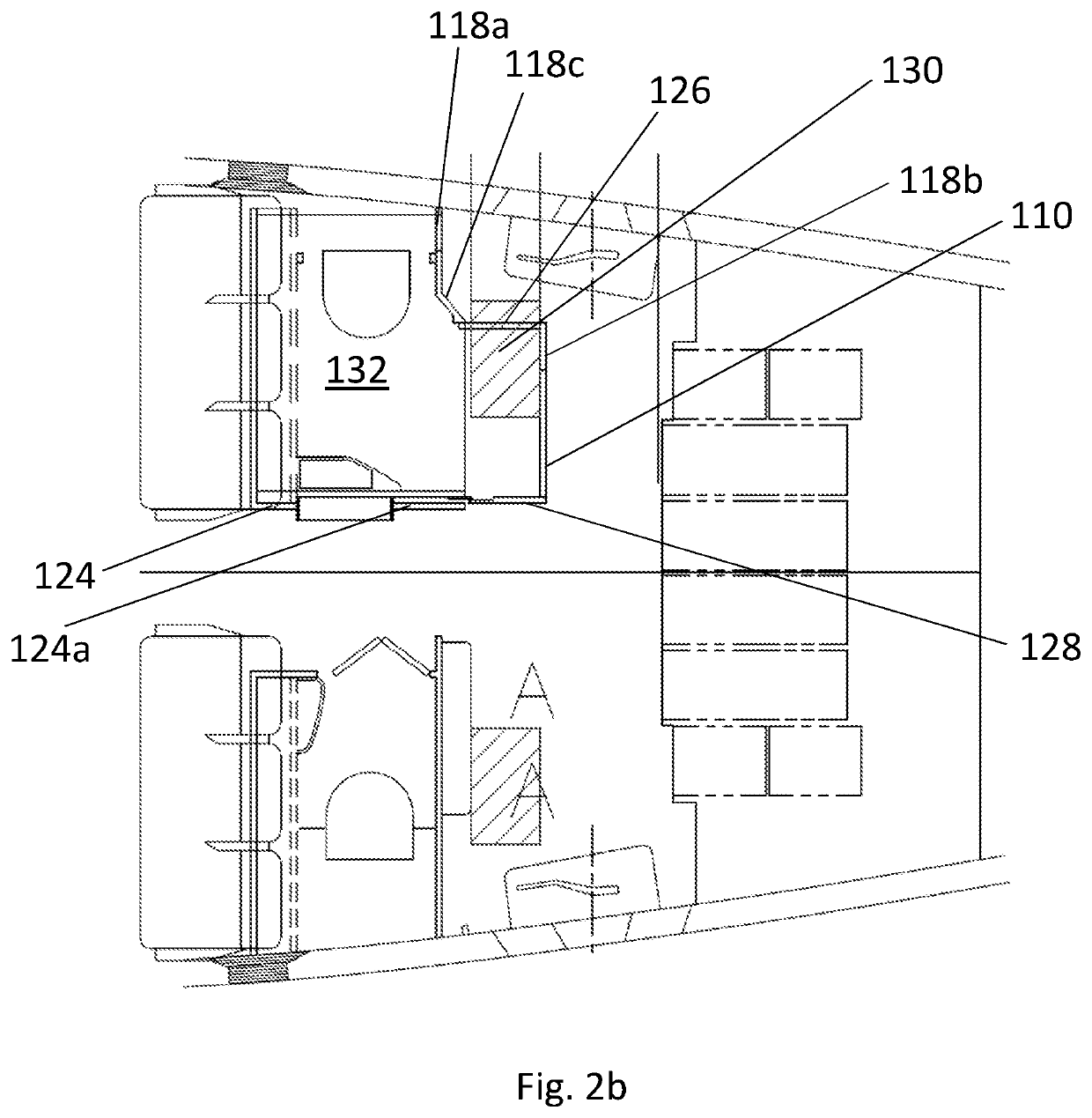
The present invention relates to improving the floor space of lavatory units in aircraft. The invention allows for the unit to be reconfigured to increase the internal floor space, while still occupying a smaller amount of space when in the able-bodied configuration. The door assembly is located on the forward side of the lavatory unit, minimizing disruption to passengers. The primary door and secondary door work together to define the perimeter wall of the unit. The invention provides a solution for optimizing floor space in aircraft lavatory units.

Problems solved by technology

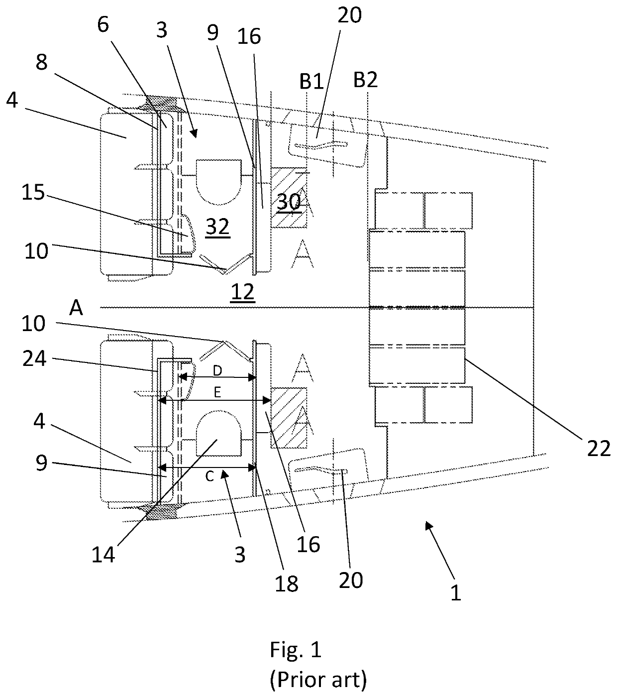
It may be that in the able-bodied configuration the lavatory unit is not suitable for use, as a lavatory unit, by a PRM.
For example, in the able-bodied configuration, the size and layout of the unit may be such that a toilet in the lavatory unit is not readily accessible and useable by a PRM.

Method used


Image

  • Prm-accessible aircraft lavatory
  • Prm-accessible aircraft lavatory
  • Prm-accessible aircraft lavatory

Examples


first embodiment

[0092]FIG. 9 shows different stages in a process of a PRM using the lavatory unit of the first embodiment with the aid of an assistant. In FIG. 9(a) the PRM is seated in the aircraft wheelchair and enters the lavatory unit 103 facing rearward via opening 148. The PRM moves forward within the lavatory unit 103 until both the PRM and the assistant are inside lavatory unit 103 and the door 110 and slidable panel 128 are brought together to close off the lavatory unit 103 from the cabin as shown in FIG. 9(b). The PRM can then transfer with the aid of the assistant from the wheelchair to the toilet 114 via the position shown in FIG. 9(c) to a final position shown in FIG. 9(d). Toilet 114 is shaped to allow a user to facing the inboard / aft corner of the lavatory unit (as shown in FIG. 9(d)). While inside the lavatory unit 103 the assistant stands with their back to door 110 within the space created by moveable wall assembly 152.

second embodiment

[0093]FIG. 10 shows different stages in a process of a PRM using a lavatory unit of a second embodiment with the aid of an assistant. Elements that are similar as between FIGS. 2 and 10 have been indicated in FIG. 10 using their reference numeral from FIG. 2 incremented by 100 (i.e. lavatory unit 103 in FIG. 2 is referred to as lavatory unit 203 in FIG. 10). The aspects of the lavatory unit 203 of FIG. 10 that differ significantly with respect to the lavatory unit 103 of FIG. 2 will be discussed here, other aspects of the lavatory unit 203 being substantially as described for lavatory unit 103. In FIG. 10(a) the lavatory unit 203 is in the able bodied configuration and, when viewed in plan, appears substantially similar to the lavatory unit 103 of FIG. 2, with the exception that the lavatory unit 203 does not include a crew seat. In the lavatory unit 203 of FIG. 10, a bi-fold panel 226 is connected between an outboard portion 218a and intermediate portion 218c of aft side 218 of per...


PUM


Abstract

An accessible lavatory unit (103) for an aircraft cabin (102) is disclosed. The lavatory unit (103) is configurable between an able-bodied configuration and a PRM-accessible configuration. In the able-bodied configuration the lavatory unit has a first internal floor space (132) and there is a cabin floor space (130) external to the lavatory unit (103). The lavatory unit (103) is expandable into the PRM-accessible configuration in which the lavatory unit (103) is expanded to have a second internal floor space (132), the second internal floor space (132) encompassing a region of the cabin floor space (130). A sink for an aircraft lavatory unit is also disclosed.

Description

FIELD OF THE INVENTION[0001]The present invention concerns the accessibility of aircraft lavatories. More particularly, but not exclusively, this invention concerns a lavatory unit for an aircraft that is configurable between an able-bodied configuration and a PRM-accessible configuration. The invention also concerns an aircraft comprising such a lavatory unit and a method of reconfiguring an aircraft lavatory unit to enable access by a PRM (Person of Reduced Mobility).BACKGROUND OF THE INVENTION[0002]It is important that PRMs (Persons of Reduced Mobility) are able to access aircraft lavatory facilities in a dignified manner. A PRM-accessible aircraft lavatory should be able to accommodate a PRM in a wheelchair and allow for a transfer from the wheelchair to the toilet. A PRM-accessible aircraft lavatory should also be able to accommodate an assistant when one is required by a PRM. Providing a lavatory unit that meets these requirements within the space limitations of a commercial p...

Claims


Application Information

Patent Timeline
IPC IPC(8): B64D11/02
CPCB64D11/02B64D2011/0046
Inventor CLUCAS, DANIEL WILLIAMHUDSON, ANTHONY RALPH PALLISERJOHNSTONE, MITCHELL ANDERWBETTELL, RAYMOND JOHN
Owner ST ENG AEROSPACE LTD
Features
  • R&D
  • Intellectual Property
  • Life Sciences
  • Materials
  • Tech Scout
  • Unparalleled Data Quality
  • Higher Quality Content
  • 60% Fewer Hallucinations
Learn More