
Plate-type evaporation air-cooling condenser

An air-cooled condenser and plate evaporation technology, which is applied in the field of heat exchange, can solve the problems of poor adaptability to working conditions, low heat exchange efficiency, and large floor space, etc., to reduce floor space, improve efficiency, and save circulating cooling water Effect

Inactive Publication Date: 2014-09-10
NORTH CHINA ELECTRIC POWER UNIV (BAODING)
View PDF4 Cites 6 Cited by
  • Summary
  • Abstract
  • Description
  • Claims
  • Application Information

AI Technical Summary

Problems solved by technology

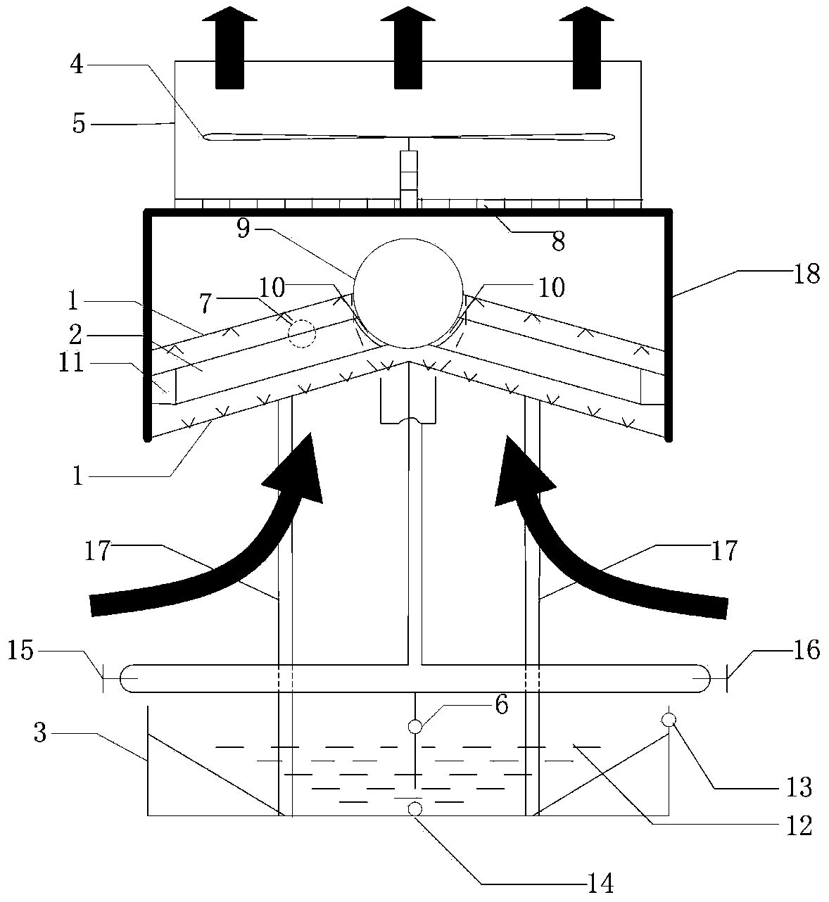
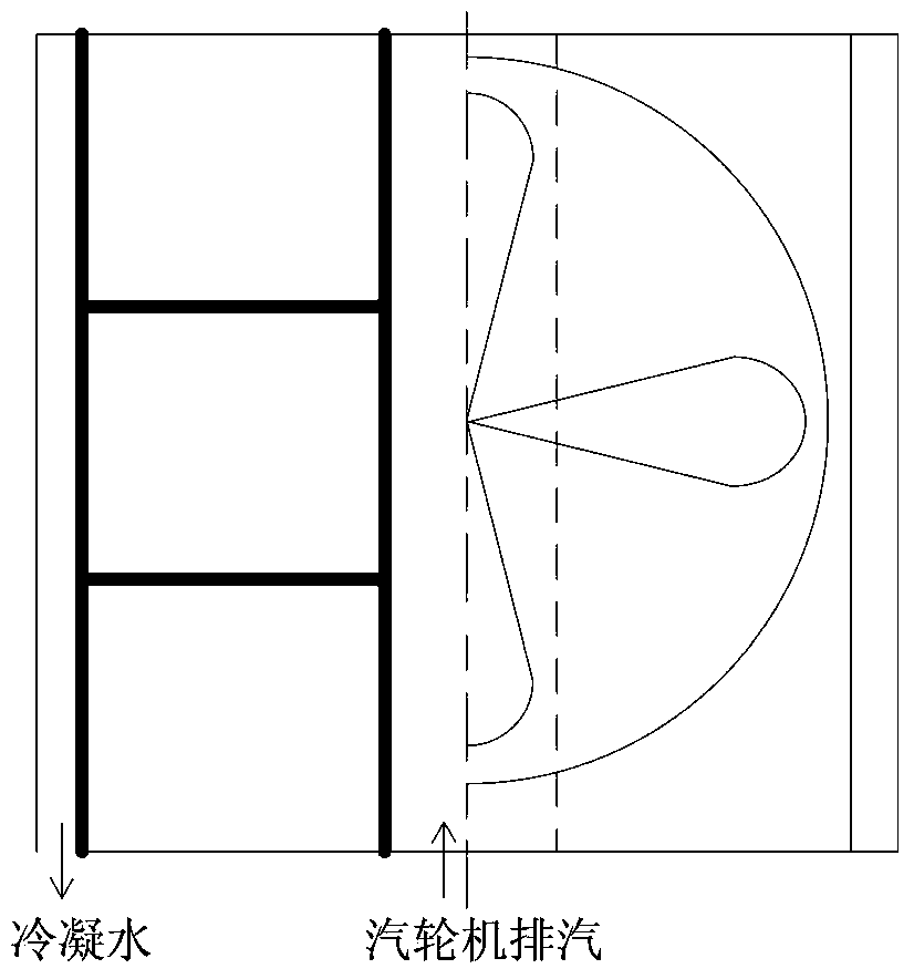
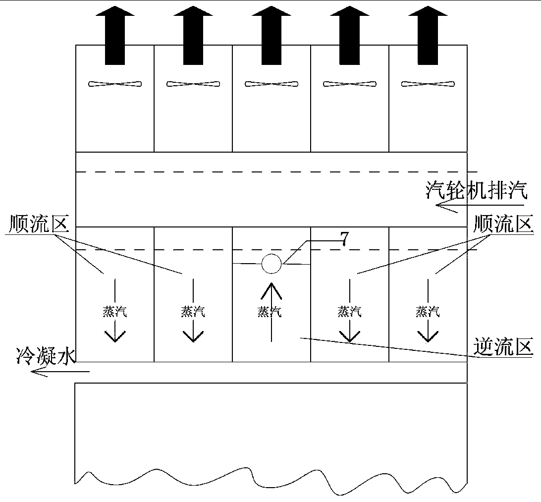
[0005] Aiming at the current problems of evaporative air-cooled condensers, such as uncompact structure, large footprint, low heat transfer efficiency, and poor adaptability to working conditions, a plate-type evaporative air-cooled condenser is proposed, which includes from top to bottom: Air outlet 5, fan 4, water baffle 8, frame 18, steam distribution pipe 9, spray device 1, steam inlet 10, water ring vacuum pump 7, two heat exchange plate bundles 2, two condensate outlets 11, Pillar 17, regulating valve 1 15, regulating valve 2 16, water supply port 13, circulating water pump 6, water storage tank 12, box body 3, sewage outlet 14;

Method used


Image

  • Plate-type evaporation air-cooling condenser
  • Plate-type evaporation air-cooling condenser
  • Plate-type evaporation air-cooling condenser

Examples


Embodiment Construction

[0020] The specific implementation manner of the present invention will be further described below in conjunction with the drawings and embodiments.

[0021] A plate-type evaporative air-cooled condenser proposed by the present invention comprises, from top to bottom: an air outlet tube 5, a fan 4, a water baffle 8, a frame 18, a steam distribution pipe 9, a spray device 1, and a steam inlet 10 , water ring vacuum pump 7, heat exchange plate bundle 2, condensed water outlet 11, pillar 17, regulating valve 1 15, regulating valve 2 16, water supply port 13, circulating water pump 6, water storage tank 12, box body 3, sewage outlet 14;

[0022] Wherein, the air outlet tube 5 is located above the frame 18, and its diameter is slightly smaller than the width of the frame, and the blower fan 4 is located in the air outlet tube 5, in order to avoid backflow of hot air and form a uniform air flow field in the box body 3; It is arranged under the fan 4 to block the water droplets conta...


PUM


Abstract

The invention belongs to the technical field of heat exchange, in particular relates to a plate-type evaporation air-cooling condenser which comprises heat exchange plate bundles, a fan, a vapor distribution tube, a spraying device, a water baffle plate and a circulation pump, wherein two heat exchange plate bundles take the shape of an inverted V; vapor inlets and condensed water outlets are respectively formed in the upper ends and the lower ends of the heat exchange plate bundles; the vapor inlets are connected with the vapor distribution tube; the condensed water outlets are connected with a condensed water pipeline; a group of spraying devices parallel to the heat exchange plate bundles are respectively arranged above and below the heat exchange plate bundles; an upper surface partitioned from the positions of the heat exchange plate bundles is covered with the water baffle plate; the fan is arranged inside an air outlet cylinder; the water baffle plate is arranged below the fan; the fan is arranged at the upper parts of the heat exchange plate bundles. Due to adoption of an air sucking structure, the structure is more compact, with the cooperation of two groups of upper and lower groups of the spraying devices, the working condition of a machine set can be flexibly adapted, and the heat exchange coefficient is about 50 times that of direct air cooling, so that not only is the heat exchange efficiency greatly improved, but also the number of condensation units is reduced, then the occupied space is reduced, and modular design is facilitated.

Description

technical field [0001] The invention belongs to the technical field of heat exchange, in particular to a plate-type evaporative air-cooled condenser. Background technique [0002] The condenser system and equipment are important components of the steam turbine unit, and its design and operating performance will directly affect the economy and safety of the entire steam turbine unit. The theoretical system of evaporative cooling and condensation has become mature. The evaporative condenser uses the fan to force the air to be discharged to the atmosphere, which ensures the evaporation of the water film outside the tube and makes full use of the latent heat of vaporization taken away by the evaporation of the cooling water. It is an efficient and energy-saving heat exchange method, and its water consumption is usually about Generally, 5% to 10% of water-cooled condensers save industrial water to a large extent. However, the traditional heat exchange tube bundles affect the ev...

Claims


Application Information

Patent Timeline
IPC IPC(8): F28B1/06
CPCY02P80/15
Inventor 魏高升苏然然邢丽婧杜小泽杨勇平
Owner NORTH CHINA ELECTRIC POWER UNIV (BAODING)
Learn More