Reservoir tank

a technology of reservoir tank and recirculating flow, which is applied in the direction of liquid degasification, separation process, lighting and heating apparatus, etc., to achieve the effect of effectively separated from the refrigerant, stably formed, and effective separation of air bubbles

Pending Publication Date: 2022-09-29
TOYOTA JIDOSHA KK +1
View PDF0 Cites 0 Cited by
  • Summary
  • Abstract
  • Description
  • Claims
  • Application Information

AI Technical Summary

Benefits of technology

[0010]In the aspect, the inflow port may be provided above the refrigerant flow port. In other words, the refrigerant flow port may be provided below the inflow port. With the configuration, the refrigerant flowing into the first chamber from the inflow port flows into the second chamber through the refrigerant flow port provided below the inflow port. At this time, the air bubbles contained in the refrigerant tend to rise due to the buoyancy against the refrigerant flowing downward. As a result, the air bubbles contained in the refrigerant stay in the first chamber for a long time, and the separation of the air bubbles by the swirling flow functions effectively.
[0011]In the aspect, a cross-sectional area perpendicular to a vertical direction of the first chamber at a height position of the inflow port may be larger than a cross-sectional area perpendicular to the vertical direction of the first chamber at a height position of the refrigerant flow port. With the above-mentioned configuration, the radius of the swirling flow at the height position of the refrigerant flow port is smaller than that at the height position of the inflow port. Therefore, at the height position of the refrigerant flow port, the centrifugal force generated in the refrigerant is larger than that at the height position of the inflow port, and thus air bubbles can be effectively separated from the refrigerant. Further, in the swirling flow formed in the first chamber, the swirling speed is gradually increased along the flow of the refrigerant from the inflow port to the refrigerant flow port. The swirling flow is likely to be stably formed, and the particle formation of air bubbles is effectively promoted.
[0012]In the aspect, the cross-sectional area perpendicular to the vertical direction of the first chamber at the height position of the inflow port may be larger than twice the cross-sectional area perpendicular to the vertical direction of the first chamber at the height position of the refrigerant flow port. With the configuration, in the swirling flow formed in the first chamber, the radius of swirling at the height position of the refrigerant flow port can be made sufficiently smaller than the radius of swirling at the height position of the inflow port. As a result, at the height position of the refrigerant flow port, the centrifugal force generated in the refrigerant can be sufficiently increased, and thus it is possible to more effectively separate air bubbles from the refrigerant.
[0013]In the aspect, the cross-sectional area perpendicular to the vertical direction of the first chamber may be changed to become smaller toward a lower side in at least a part between the height position of the inflow port and the height position of the refrigerant flow port. In this case, the cross-sectional area perpendicular to the vertical direction of the first chamber may be decreased stepwise or continuously between the height position of the inflow port and the height position of the refrigerant flow port. With the above-mentioned configuration, in the swirling flow formed in the first chamber, the swirling speed is changed smoothly along the vertical direction, and thus the swirling flow of the refrigerant is stable and the particle formation of air bubbles is further promoted.
[0014]In the aspect, a volume of the first chamber may be smaller than a volume of the second chamber. With the above-mentioned configuration, the time that the refrigerant stays in the second chamber is longer than the time that the refrigerant stays in the first chamber. Air bubbles are removed from the refrigerant in the second chamber, and thus it is possible to sufficiently remove air bubbles from the refrigerant by prolonging the time that the refrigerant stays in the second chamber.

Problems solved by technology

In the above-mentioned reservoir tank, the shape of the reservoir tank is limited to a cylindrical shape, which requires a relatively large space for disposing the reservoir tank.

Method used


Image

  • Reservoir tank
  • Reservoir tank
  • Reservoir tank

Examples


Embodiment Construction

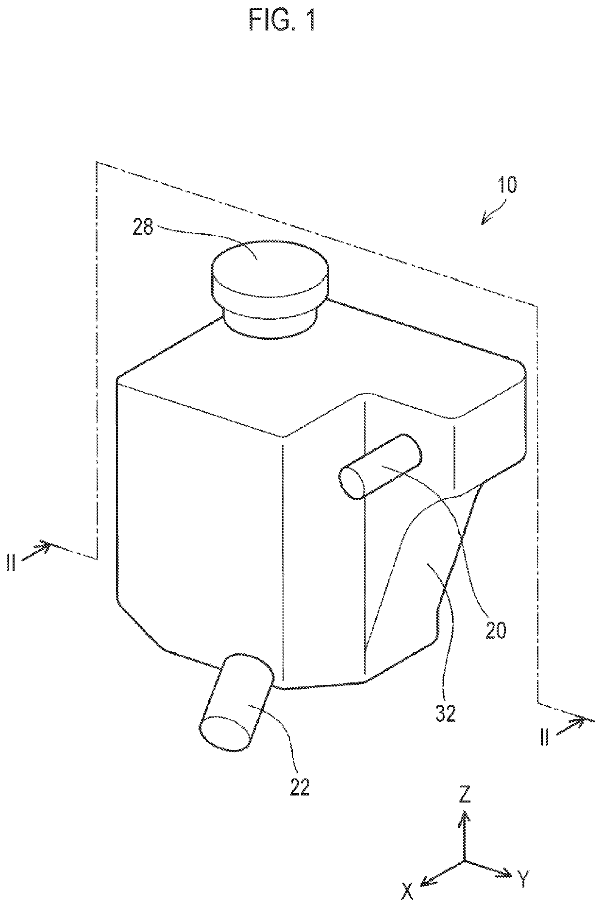
[0021]A reservoir tank 10 of an embodiment will be described with reference to the drawings. The reservoir tank 10 of the embodiment is provided in a circuit in which a refrigerant (also referred to as a “heat medium”), such as coolant, circulates. When the refrigerant 80 flows in and out of the circuit, the reservoir tank 10 stores surplus refrigerant 80 and removes air bubbles 70 from the refrigerant 80. As an example, the reservoir tank 10 can be used in a vehicle thermal management system. In this case, in the reservoir tank 10, the air bubbles 70 are removed from the refrigerant 80 when the refrigerant 80 that cools each part of the vehicle flows in and out. Although not particularly limited, the reservoir tank 10 is made of resin. In the following, as illustrated in FIG. 1, a vertically upward direction indicates a Z direction, one direction parallel to a horizontal plane indicates an X direction, and a direction parallel to the horizontal plane and orthogonal to the X directi...


PUM

PropertyMeasurementUnit
radius of curvatureaaaaaaaaaa
radiusaaaaaaaaaa
heightaaaaaaaaaa

Abstract

A reservoir tank includes a first chamber, a second chamber, an inflow port coupled to the first chamber, an outflow port coupled to the second chamber, a partition wall provided to separate the first chamber and the second chamber from each other, and a refrigerant flow port provided in the partition wall to connect the first chamber and the second chamber to each other. When the reservoir tank is viewed in a plan view, at least a portion of a range of an inner wall of the first chamber facing the inflow port is curved in an arc shape.

Description

CROSS-REFERENCE TO RELATED APPLICATION[0001]This application claims priority to Japanese Patent Application No. 2021-049128 filed on Mar. 23, 2021, incorporated herein by reference in its entirety.BACKGROUND1. Technical Field[0002]The disclosure relates to a reservoir tank.2. Description of Related Art[0003]Japanese Unexamined Patent Application Publication No. 2020-067082 (JP 2020-067082 A) discloses a reservoir tank. The reservoir tank has a cylindrical shape and includes a first chamber to which an inflow port is coupled, a second chamber to which an outflow port is coupled, and a partition wall separating the first chamber and the second chamber from each other. The first chamber and the second chamber are coupled to each other via a refrigerant flow port provided in the partition wall. The reservoir tank further includes a cylindrical swirling flow forming portion between the inflow port and the first chamber, and two holes coupled to the first chamber are provided on concentri...

Claims


Application Information

Patent Timeline
Patent Type & Authority Applications(United States)
IPC IPC(8): F25B43/04F25B43/00B01D19/00
CPCF25B43/04F25B43/006B01D19/0057B01D19/02B60H1/00507
Inventor NISHIOKA, HIDEO
Owner TOYOTA JIDOSHA KK
Why Eureka
Try Eureka