Monoblock sensor body and method of its manufacturing

Pending Publication Date: 2022-09-29
METTLER TOLEDO GMBH
View PDF0 Cites 0 Cited by
  • Summary
  • Abstract
  • Description
  • Claims
  • Application Information

AI Technical Summary

Benefits of technology

The patent text describes a sensor body that can increase accuracy without compromising its stiffness. This is achieved by connecting mounting holes with the same closest flexure point section, which forms a cavity region inside the body. This helps protect sensitive parts of the sensor from deformation caused by mechanical stress and ensures optimal performance.

Problems solved by technology

Constructions of that shown f.i. in DE 196 05 087 A1 have been identified as being problematic for stiffness and stability due to slots cutted from the upper respectively lower side (in height direction) into the monoblock body.

Method used


Image

  • Monoblock sensor body and method of its manufacturing
  • Monoblock sensor body and method of its manufacturing
  • Monoblock sensor body and method of its manufacturing

Examples


Embodiment Construction

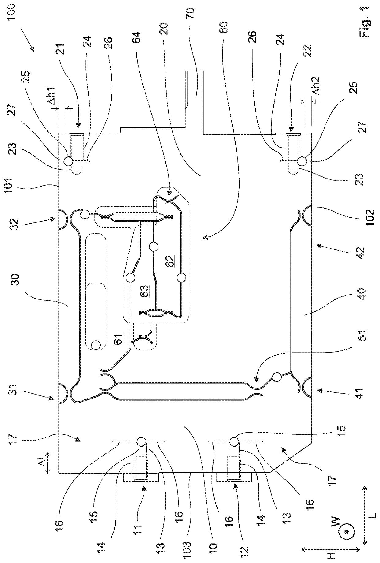
[0037]In FIG. 1, a monoblock sensor body 100 is shown in a side view but still with indicated mounting holes, the direction of view corresponding to the width direction W and the paper plane of FIG. 1 corresponding to a height-length-plane. The sensor body 100 comprises, as readily recognizable by the person skilled in the art, a Roberval mechanism having a fixed column 20 and a movable column 10 connected to fixed column 20 by parallel upper beams 30 and 40. The bending section for this parallel construction is denoted by flexure point section 31 between movable column 10 and upper beam 30 (upper left flexure point section), (upper right) flexure point section 32 between upper beam 30 and fixed column 20, (lower left) flexure point section 41 between movable column 10 and lower beam 40, and (lower right) flexure point section 42 between lower beam 40 and fixed column 20.

[0038]Coupled to movable column 10 by a coupling with lower coupling mount 51 is a lever arrangement 60, having i...


PUM


Abstract

A monoblock sensor body of a load cell based on an electromagnetic force compensation mechanism has a Roberval mechanism. Mounting portions mount the fixed column to a housing side of a weighing module, and mount a load receiving member to the movable column. At least one of the mounting portions has at least one mounting hole that extends predominantly orthogonal to the load direction. One of the flexure point sections is closest to the mounting hole. A cavity associated with at least one of the mounting portions reduces an available solid angle for straight propagation paths that run from the inner thread to one or more of: the closest flexure point section, the coupling and the closest fulcrum. A material boundary of the body closes the cavity over at least a bridging width versus the height-side end of the body corresponding to the closest flexure point section.

Description

TECHNICAL FIELD[0001]The present invention is in the field of load detection. In particular, the invention is related to the kind of load detections where a Roberval mechanism is involved for receiving the load with its movable column, and a lever arrangement is provided, coupled to the movable column of the Roberval mechanism, and the load measuring principle is that of the electromagnetic force compensation, a corresponding mechanism being connected to the lever arrangement. Even more specifically, the invention relates to those types of load cells where the Roberval mechanism and a lever mechanism is defined within one single block of material, that is within a monoblock sensor body.[0002]Even more specifically, the invention is related to a monoblock sensor body of a load cell based on an electromagnetic force compensation mechanism, comprising a Roberval mechanism, a lever arrangement coupled on the one hand side by a coupling to the movable column of the Roberval mechanism and...

Claims


Application Information

Patent Timeline
IPC IPC(8): G01G11/00B26F3/00
CPCG01G11/003B26F3/004G01G21/00G01G23/00G01G7/02G01G21/244
Inventor REBER, DANIELLANG, CHRISTOPH
Owner METTLER TOLEDO GMBH
Why Eureka
Try Eureka