Method For Controlling Robot, Robot System, And Storage Medium

Pending Publication Date: 2022-10-06
SEIKO EPSON CORP
View PDF0 Cites 0 Cited by
  • Summary
  • Abstract
  • Description
  • Claims
  • Application Information

AI Technical Summary

Benefits of technology

[0008]A robot system according to the present disclosure includes: a base; a robot arm coupled to the base; a drive unit including a motor for driving the robot arm; and a control unit configured to control an actuation of the robot arm. The control unit includes an acquisition unit configured to acquire weight information, which is information on a weight of an end effector i

Problems solved by technology

In recent years, automation of work that has been done manually is accelerating by various robots and robot peripheral devices due to an increase in labor costs and lack of talents in a factory.
Howev

Method used


Image

  • Method For Controlling Robot, Robot System, And Storage Medium
  • Method For Controlling Robot, Robot System, And Storage Medium
  • Method For Controlling Robot, Robot System, And Storage Medium

Examples


Example

[0023]Hereinafter, a method for controlling a robot, a robot system, and a non-transitory computer-readable storage medium storing a program for controlling a robot according to the present disclosure will be described in detail based on a preferred embodiment shown in the accompanying drawings.

Embodiment

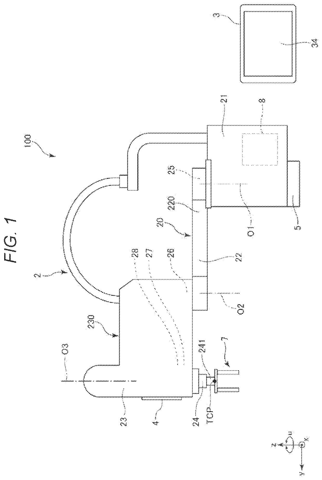
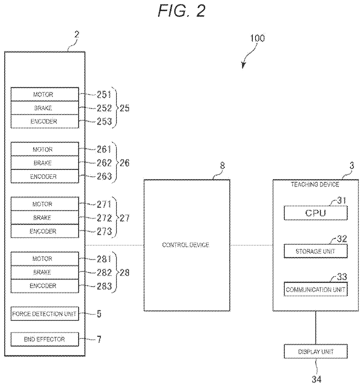
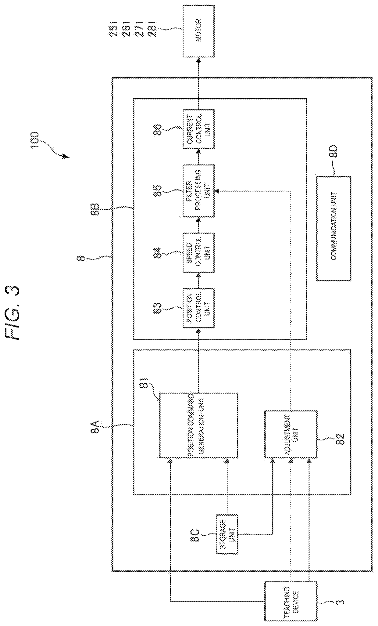
[0024]FIG. 1 is a schematic configuration diagram of a robot system according to the present disclosure. FIG. 2 is a block diagram of the robot system shown in FIG. 1. FIG. 3 is a block diagram of a control device shown in FIG. 1. FIGS. 4 to 7 are diagrams showing examples of tables referred to by an adjustment unit. FIGS. 8 and 9 are side views showing positional relationships between a gravity center of a robot arm of a robot and a gravity center of an end effector shown in FIG. 1. FIGS. 10 and 11 are diagrams showing overall shapes of the robot arm shown in FIG. 1. FIG. 12 is a flowchart illustrating a method for controlling a robot according to the present disclosure.

[0025]In FI...


PUM


Abstract

Provided is a method for controlling a robot including a base, a robot arm coupled to the base, and a drive unit including a motor for driving the robot arm. The method includes a first step of acquiring weight information including information on a weight of an end effector installed on the robot arm and a weight of an object to be worked by the end effector, a second step of determining a frequency component to be removed from a drive signal for driving the motor based on the weight information acquired in the first step, and a third step of removing the frequency component determined in the second step from the drive signal to generate a correction drive signal.

Description

[0001]The present application is based on, and claims priority from JP Application Serial Number 2021-062360, filed Mar. 31, 2021, the disclosure of which is hereby incorporated by reference herein in its entirety.BACKGROUND1. Technical Field[0002]The present disclosure relates to a method for controlling a robot, a robot system, and a non-transitory computer-readable storage medium storing a program for controlling a robot.2. Related Art[0003]In recent years, automation of work that has been done manually is accelerating by various robots and robot peripheral devices due to an increase in labor costs and lack of talents in a factory. As the various robots, for example, a robot as disclosed in JP-A-2001-293638 is known.[0004]The robot of JP-A-2001-293638 performs the following operations in order to reduce a vibration of an arm. First, the vibration is measured by tapping and vibrating an end effector provided on the arm. Next, a natural frequency of the arm is calculated based on a...

Claims


Application Information

Patent Timeline
IPC IPC(8): B25J9/16B25J9/04
CPCB25J9/1638B25J9/1692B25J9/043B25J9/1602B25J9/1664B25J9/126B25J9/042G05B2219/40301G05B2219/39188G05B2219/39195B25J9/1641
Inventor SEJIMO, ISAMU
Owner SEIKO EPSON CORP
Why Eureka
Try Eureka