
Corner patch

Pending Publication Date: 2022-10-06
AUTOTECH ENG SL
View PDF0 Cites 0 Cited by
  • Summary
  • Abstract
  • Description
  • Claims
  • Application Information

AI Technical Summary

Benefits of technology

This patent introduces a reinforcement element for a profile used to form a B-pillar for a vehicle. The reinforcement element is made up of two elongated strips of material that are inter-connected at at least one attachment area for door hinges. This design makes it easy to handle the attachment of the strips to the profile and provides a reinforcement aspect at an area that is exposed to forces when a door is handled. The strips may be interconnected at an attachment area of an upper or lower door hinge, depending on the needs of the vehicle door attachment. Overall, this reinforcement element design provides increased strength and durability to the vehicle's profile, improving its overall performance and safety.

Problems solved by technology

A drawback with this solution is that a number of loose reinforcement members have to be handled and placed on a base member or blank in order to be attached by e.g. welding.
From a view of mass-production, this is not optimal since it requires multiple fixtures or clamping members that hold a plurality of reinforcement members during attachment.

Method used


Image

  • Corner patch
  • Corner patch
  • Corner patch

Examples


first embodiment

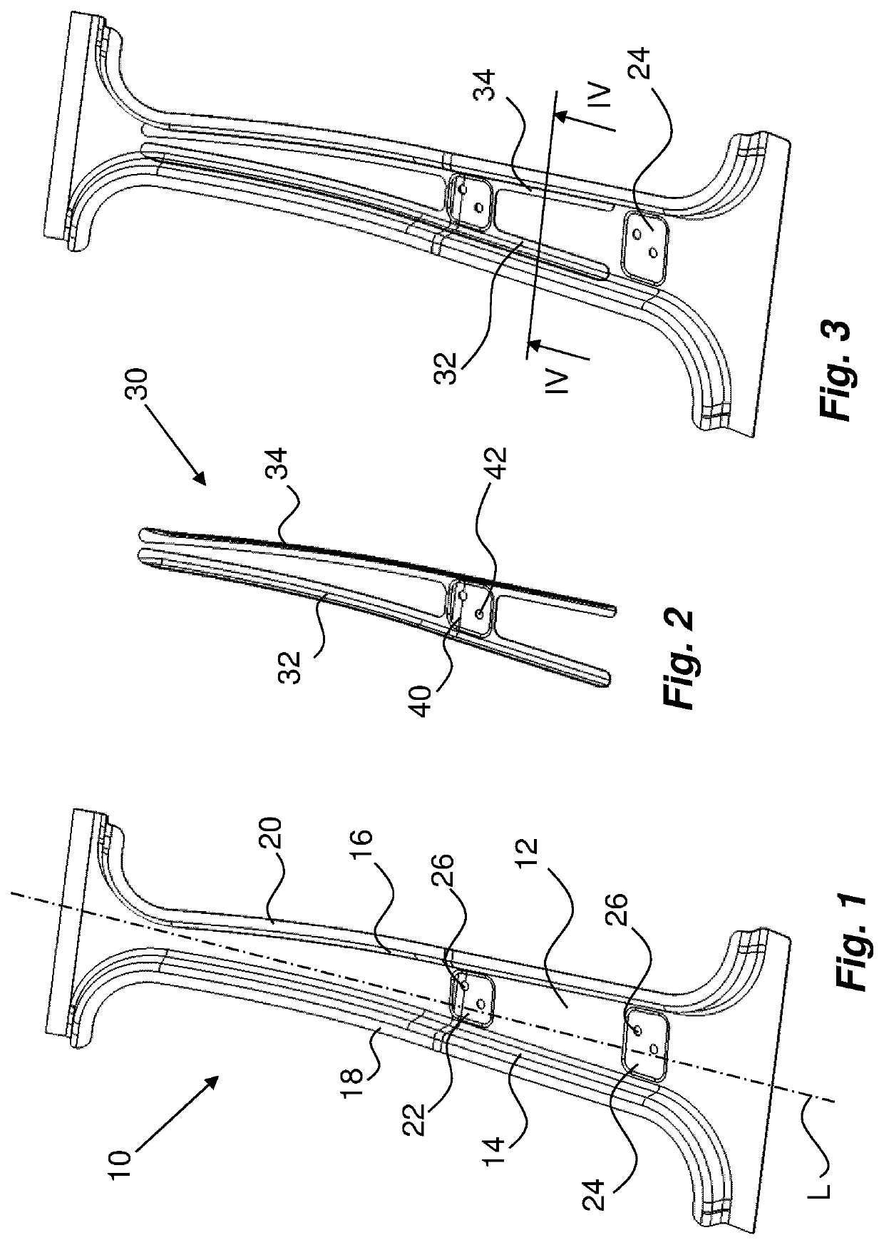
[0031]In order to enhance the strength of the profile 10 and to provide it with desired handling characteristics of impact forces without undue addition of weight to the finished B-pillar, a reinforcement element 30 is attached to the profile 10. In the first embodiment shown in FIGS. 2 and 3, the reinforcement element 30 comprises two elongated strips 32, 34. The strips 32, 34 are designed such and have such a distance between them that they will cover at least transition areas 36, 38 between the central flange and the sides, see FIG. 4, such that one strip 32 covers one transition area 36 between the central flange 12 and one side 14 and the other strip 34 covers another transition area 38 between the central flange 12 and the other side 16. Thus, with this solution, there will be a central area of the central flange 12 that is uncovered by the reinforcement element. However, the two strips 32, 34 are interconnected at least in one position. This is on the one hand for easier hand...

second embodiment

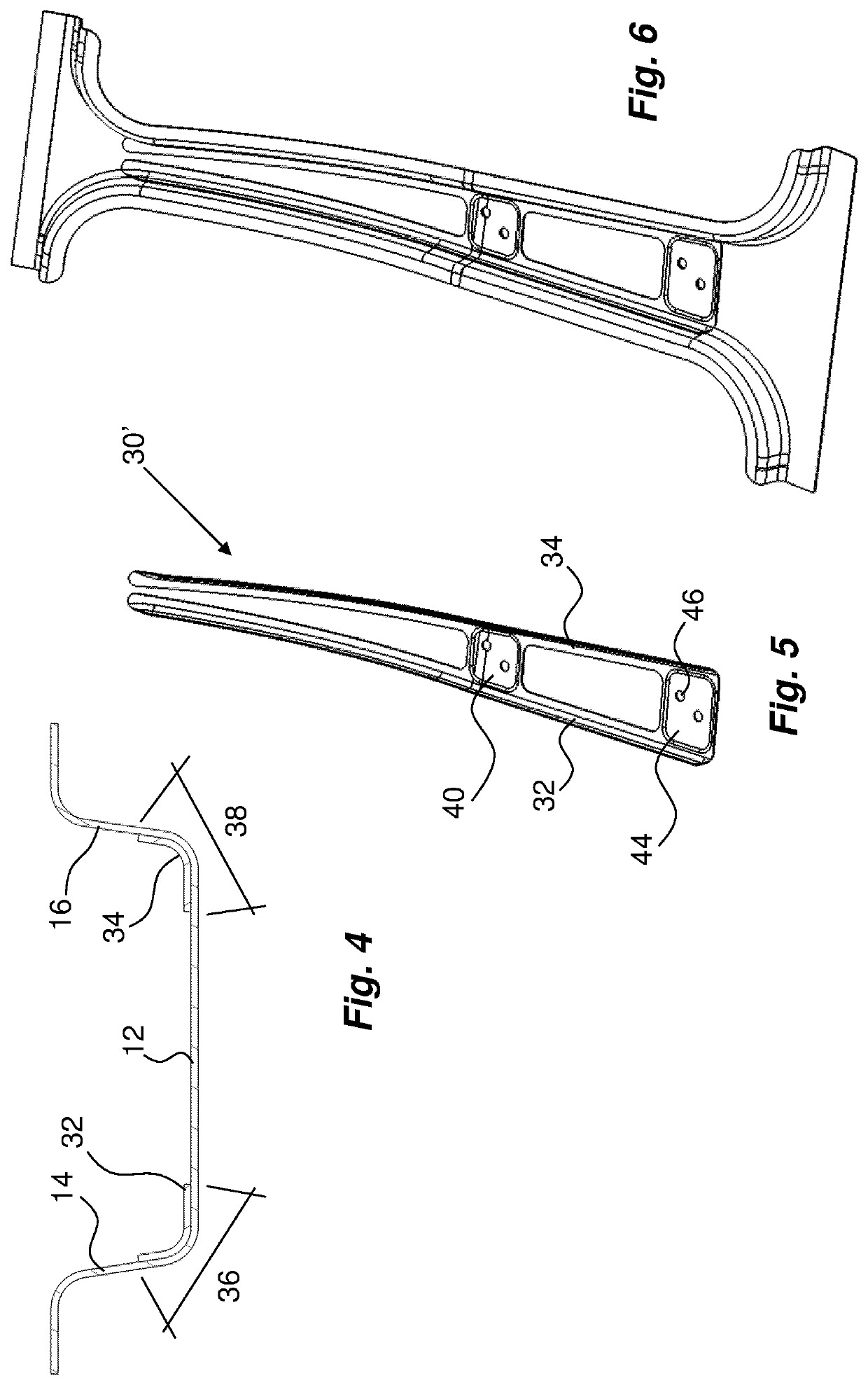
[0033]a reinforcement element 30′ is shown in FIGS. 5-6. Here the strips 32, 34 of the reinforcement element 30′, apart from the first bridging component, are interconnected at a lower end thereof with a second bridging component 44, which second bridging component 44 is arranged to cover the lower attachment area 24 for a lower door hinge. Also here the second bridging component 44 is preferably provided with fastening elements 46 of the same type and orientation as the fastening elements 26 of the attachment area 24 of the lower door hinge in the profile 10. With this solution, both attachment areas 22, 24 for door hinges are reinforced by the reinforcement element as seen in FIG. 6.

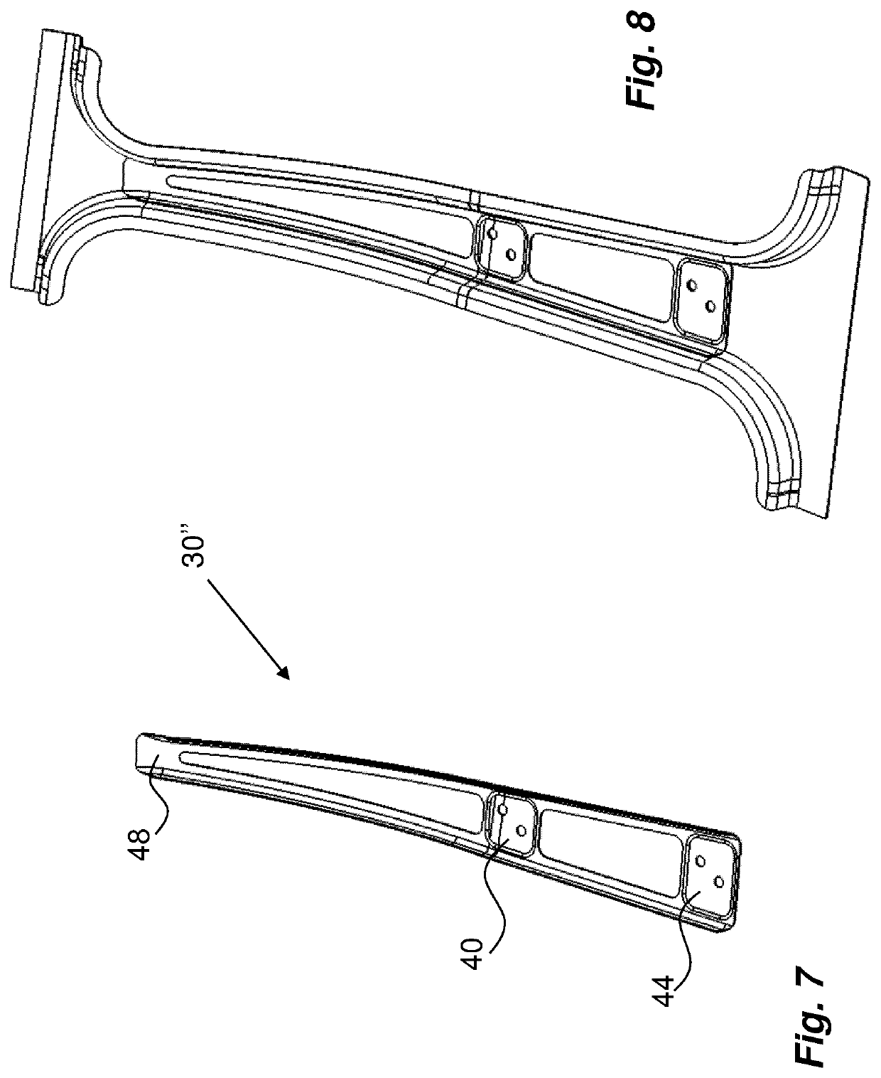
[0034]In order to further enhance and / or customize the strength and deformation resistance properties of the B-pillar, the reinforcement element may be provided with further bridging components. A third embodiment of a reinforcement element 30″ is shown in FIGS. 7-8. Here the strips 32, 34, apart from ...


PUM


Abstract

The present application relates to a reinforcement element (30) arranged to be attached to a profile (10) for forming a B-pillar for a vehicle, which profile (10) is arranged with attachment areas (22, 24) for door hinges, characterised in that the reinforcement element (30) is designed with two elongated strips (32, 34) of material, wherein the strips (32, 34) are inter-connected at least at one attachment area (22) for door hinges when the reinforcement element (30) is attached to profile (10), wherein the profile (10) is hat-shaped with a central flange (12) and two sides (14, 6), and wherein each strip (32, 34) is attached to the transition area (36, 38) between the central flange (12) and a side (14, 16). The present application also 10 relates to a B-pillar provided with the reinforcement element as well as a method of manufacturing a B-pillar with the reinforcement element.

Description

TECHNICAL AREA[0001]The present invention relates to a reinforcement element for a pillar for a vehicle and in particular a so-called B-pillar forming a part of the body of a motor vehicle such as a car.BACKGROUND OF INVENTION[0002]The pillars of motor vehicles are required to withstand high strain such as during a collision. Modern designs comprise pillars that are reinforced by adding material to certain areas along the extension. For example, it is known to place sheet metal reinforcements on a sheet metal blank, weld them together and then form a pillar by hot forming and hardening in a press hardening process. This is for instance known from WO2014 / 017961. Here a reinforcement plate is attached to a plate blank for forming a B-pillar. The reinforcement plate has a design such that at least ¼ of its length has a width corresponding to the hat profile of the B-pillar and then narrows down at both its ends, whereby it is not extending the full width. With this design, good collisi...

Claims


Application Information

Patent Timeline
IPC IPC(8): B62D25/04B62D29/00B60J5/04
CPCB62D25/04B62D29/005B60J5/042B60J5/0444B60J5/0431B62D27/023
Inventor BODIN, HANSHOLMBERG, MARTINJOHANSSON, JOAKIMNAYSTRÖM, SOFIA
Owner AUTOTECH ENG SL
Features
  • Generate Ideas
  • Intellectual Property
  • Life Sciences
  • Materials
  • Tech Scout
  • Unparalleled Data Quality
  • Higher Quality Content
  • 60% Fewer Hallucinations
Learn More