Window Treatment With Outdoor Temperature Indication Arrangement

Active Publication Date: 2022-10-06
CHEUNG CANDICE
View PDF33 Cites 1 Cited by
  • Summary
  • Abstract
  • Description
  • Claims
  • Application Information

AI Technical Summary

Benefits of technology

The present invention provides a window treatment that has the following technical effects: a sealed thermal insulating layer to prevent color change of temperature-sensitive portions in response to interior temperature, improved versatility and efficiency, and a reduction in manufacturing costs when incorporating outdoor temperature indication arrangements with existing window treatments.

Problems solved by technology

However, the existing window treatments have a common drawback that it forms an environmental barrier to block any exterior condition.
For example, the user will not instantaneously know the current weather condition or outdoor temperature when he or she wakes up.

Method used


Image

  • Window Treatment With Outdoor Temperature Indication Arrangement
  • Window Treatment With Outdoor Temperature Indication Arrangement
  • Window Treatment With Outdoor Temperature Indication Arrangement

Examples


first embodiment

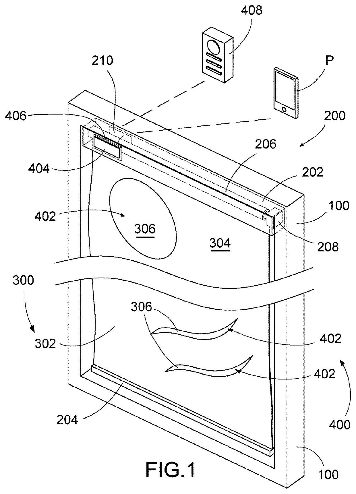
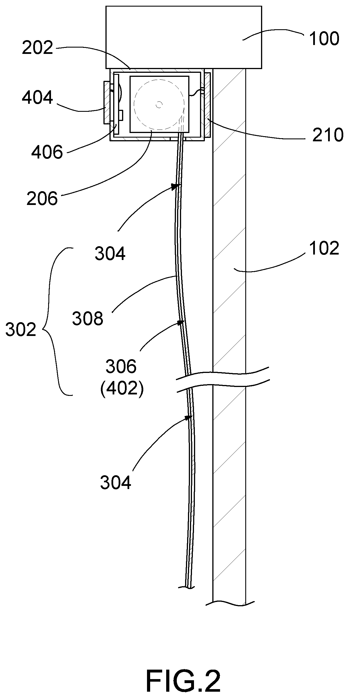
[0020]Referring to FIGS. 1 and 2, a window treatment according to the present invention is designed for installing into a window which is constructed to have a window frame 100 and a window glass 102 within the window frame 100. The window treatment of the present invention comprises a mounting unit 200, a shade unit 300, and an outdoor temperature indication arrangement 400.

[0021]The mounting unit 200 comprises a top member 202 is arranged for mounting at a ceiling of the window frame 100 via conventional screws or other suitable fasteners. The mounting unit 200 is an elongated top supporting bar having a length slightly smaller than an interior width of the window frame 100.

[0022]The shade unit 300 is supported by the top member 202 of the mounting unit 200 and is downwardly suspended from the mounting unit 200, wherein the shade unit 300 is moved between a closed position and an opened position. At the closed position, the shade unit 300 is moved for covering the window glass 102...
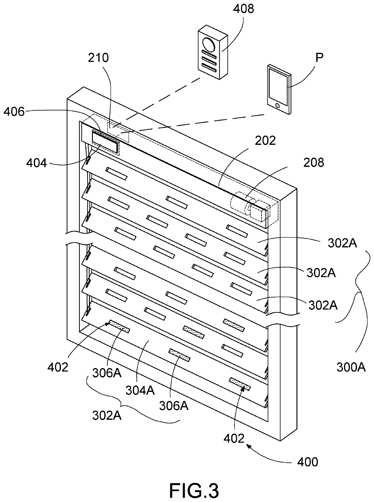
second embodiment

[0038]In the second embodiment, the shade unit 300A comprises a plurality of window slats 302A spacedly suspended below the top member 202, wherein the window slats 302A, which are horizontal slats, are moved between the closed position and the opened position. At the closed position, the window slats 302A are slanted and coupled with each other edge-to-edge or covering the window glass 102. At the opened position, the window slats 302A are spaced apart from each other for allowing light ray passing through a gap between every two of the window slats 302A. Furthermore, the window slats 302A can be upwardly lifted toward the top member 202 to overlap with each other for uncovering the window glass 102. Therefore, the shade unit 300A can be moved at two different opened positions. It is worth mentioning that at the closed position, the window slats 302A are arranged to closely cover the window glass 102, so that a clearance between the window slats 302A and the window glass 102 is min...


PUM

PropertyMeasurementUnit
Temperatureaaaaaaaaaa
Transparencyaaaaaaaaaa
Sensitivityaaaaaaaaaa

Abstract

The window treatment includes a top member, a shade unit, and an outdoor temperature indication arrangement. The top member is adapted for mounting at a ceiling of the window frame. The shade unit is downwardly suspended from the top member and being moved between a closed position and an opened position, wherein at the closed position, the shade unit is moved for covering the window glass to control an amount of light in a space, and at the opened position, the shade unit is moved for uncovering the window glass. The outdoor temperature indication arrangement is formed with the shade unit for indicating an outdoor temperature when the shade unit is moved at the closed position.

Description

BACKGROUND OF THE PRESENT INVENTIONField of Invention[0001]The present invention relates generally to window treatments, and more particularly to a window treatment with an outdoor temperature indication arrangement, which provides multiple functions of blocking external light through a window, offering great insulation, and indicating outdoor temperature at the same time.Description of Related Arts[0002]Existing window treatments are adapted to be mounted onto window frames, wherein the window treatment generally comprises a frame supporter affixed to a ceiling of the window frame and a shading element suspended below the frame supporter for covering the window to block the external light passing through the window. Accordingly, the shading element can be curtains, draperies, shades, blinds and shutters. Due to the material properties of the shading element, the shading element is designed to selectively block at least a portion of light passing therethrough. For example, a light f...

Claims


Application Information

Patent Timeline
IPC IPC(8): E06B9/264E06B9/40C09D5/26E06B9/70G01W1/00
CPCE06B9/264E06B9/40C09D5/26E06B9/70G01W1/00E06B2009/2476E06B9/30E06B9/386E06B9/322E06B2009/3222E06B9/42G01K11/12
Inventor CHEUNG, CANDICE
Owner CHEUNG CANDICE
Why Eureka
Try Eureka