Eureka AIR delivers breakthrough ideas for toughest innovation challenges, trusted by R&D personnel around the world.

Blender

Pending Publication Date: 2022-10-13
LG ELECTRONICS INC
View PDF0 Cites 0 Cited by
  • Summary
  • Abstract
  • Description
  • Claims
  • Application Information

AI Technical Summary

Benefits of technology

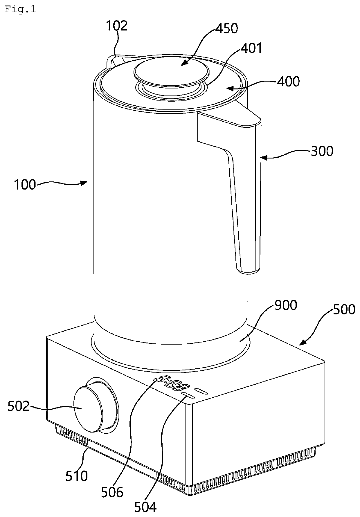
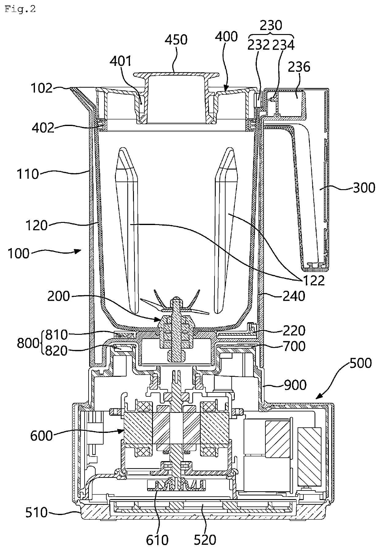
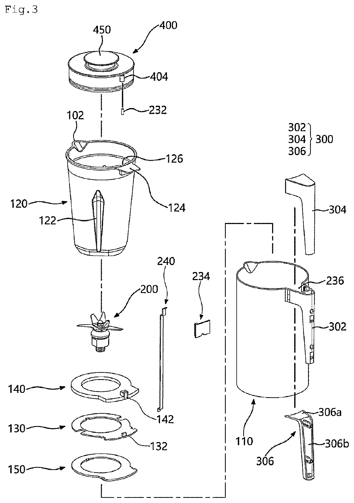
The patent proposes a blender that reduces noise caused by the vortex occurring at the back of a blade. The blade has a sawtooth-shaped corrugation on its leading edge portion. This design allows for efficient cutting of soft food without removing it from its place, improving the crushing function of the blender.

Problems solved by technology

However, in the structure of such a conventional container body or blade, it takes a long time to crush food and the crushing or mixing of food is not properly performed.
Accordingly, the crushing and mixing of entire food are not properly performed, and further, it takes a long time to crush food.
However, even in such a structure, an area in which food is cut by the blades is limited, so it takes a considerable time to process and mix food.
However, even in such a conventional technology, the crushing or noise problem of the blades is not resolved.
That is, in the conventional technology, by bending the blades upward and downward, an area in which food is crushed by the blades is increased to some degree, but only four blades are provided to crush food and thus the crushing ability of food by the blades is not considerably improved.
However, even in this technology, each of the blades is configured as a flat plate having a predetermined thickness, and only the number of the blades is increased, so noise is increased due to the multiple blades.

Method used


Image

  • Blender
  • Blender
  • Blender

Examples


second embodiment

[0373]In the main blade unit 250, five corrugated shapes are formed on the main blade 250b of the main blade unit 250.

[0374]FIGS. 24 and 25 respectively illustrate the third and fourth embodiments of the configuration of the main blade unit 250. That is, FIGS. 24 and 25 respectively illustrate the perspective views of the main blade unit 250 according to the third and fourth embodiments.

[0375]As illustrated in these drawings, corrugated shapes may be formed on the leading edge portion of the blade of the blade unit 250 or 252. Furthermore, these corrugated shapes may be formed on the inclined surface 250c or 250c′. The corrugated shapes formed on the main blade 250b of the main blade unit 250 may have curvatures or have the shape of sawteeth.

[0376]Specifically, four corrugated shapes are formed on the main blade of the main blade unit 250 illustrated in FIG. 24 according to the third embodiment, and three corrugated shapes are formed on the main blade of the main blade unit 250 illu...

fourth embodiment

[0377]In the fourth embodiment illustrated in FIG. 25, three corrugated shapes are formed on the main blade, and these corrugated shapes may be formed on the inner side of the main blade. Accordingly, corrugated shapes may not be formed on the outer side (an end portion) of the main blade, and thus the end portion of the main blade may faithfully perform a unique cutting function thereof. That is, the end portion of the main blade may be used to easily cut hard or large materials (food), and the sawtooth-shaped corrugation of the main blade may be used to effectively cut soft materials, thereby improving ability to cut various materials by the main blade.

[0378]FIGS. 26, 27A, 27B, and 28 illustrate views for describing a bending angle α and a twisting angle β formed on the blade constituting the blender according to the embodiment of the present disclosure. That is, FIG. 26 illustrates a perspective view of a basic blade unit constituting the blender according to the embodiment of th...


PUM


Abstract

Proposed is a blender in which multiple blades have different bending or twisting angles. The blender includes a container body in which food is received, a main body provided under the container body and configured to support the container body, a container lid mounted detachably to the upper surface of the container body and configured to open and close the upper surface of the container body, and a blade assembly which crushes food contained in the container body by blades. The blade assembly includes a main blade unit having multiple main blades, and an auxiliary blade unit having an auxiliary blade located between the multiple main blades, wherein the multiple main blades have bending or twisting angles different from each other. In such a blender, the cutting efficiency of food materials is improved and noise is decreased.

Description

CROSS REFERENCE TO RELATED APPLICATION[0001]The present application claims priority to Korean Patent Application No. 10-2021-0046691, filed Apr. 9, 2021, the entire contents of which are incorporated herein for all purposes by this reference.BACKGROUND OF THE INVENTIONField of the Invention[0002]The present disclosure relates generally to a blender. More particularly, the present disclosure relates to a blender in which multiple blades are configured to bend or twist at angles different from each other.Description of the Related Art[0003]Generally, a blender is referred to as a mixer or crusher, and is mainly used for crushing or chopping food contained in a container body by rotating blades by the rotation of a motor.[0004]In a normal blender, a main body having a motor operated by electricity is located at the lower side of the blender, and the container body receiving food is seated on the upper side of such a main body. Blades crushing or chopping food are provided inside the co...

Claims


Application Information

Patent Timeline
IPC IPC(8): A47J43/07A47J43/046B01F27/808B01F27/90B01F27/112
CPCA47J43/0722A47J43/046B01F27/808B01F27/90B01F27/112B01F2101/06A47J43/0716
Inventor KANG, KI JOONGPARK, HYUN WOOKIM, YOUNG SOOKIM, YANG HO
Owner LG ELECTRONICS INC
Why Eureka
Eureka Blog
Learn More