
A marine construction and a method for constructing the same

a construction method and technology for artificial surfaces, applied in vessel construction, special-purpose vessels, groynes, etc., can solve the problems of limiting the possibility of stable surfacing the constructed area, the limit of loading usage, and the loss of fill material

Pending Publication Date: 2022-10-13
ISRAEL PORTS DEV & ASSETS CO LTD
View PDF15 Cites 0 Cited by
  • Summary
  • Abstract
  • Description
  • Claims
  • Application Information

AI Technical Summary

Benefits of technology

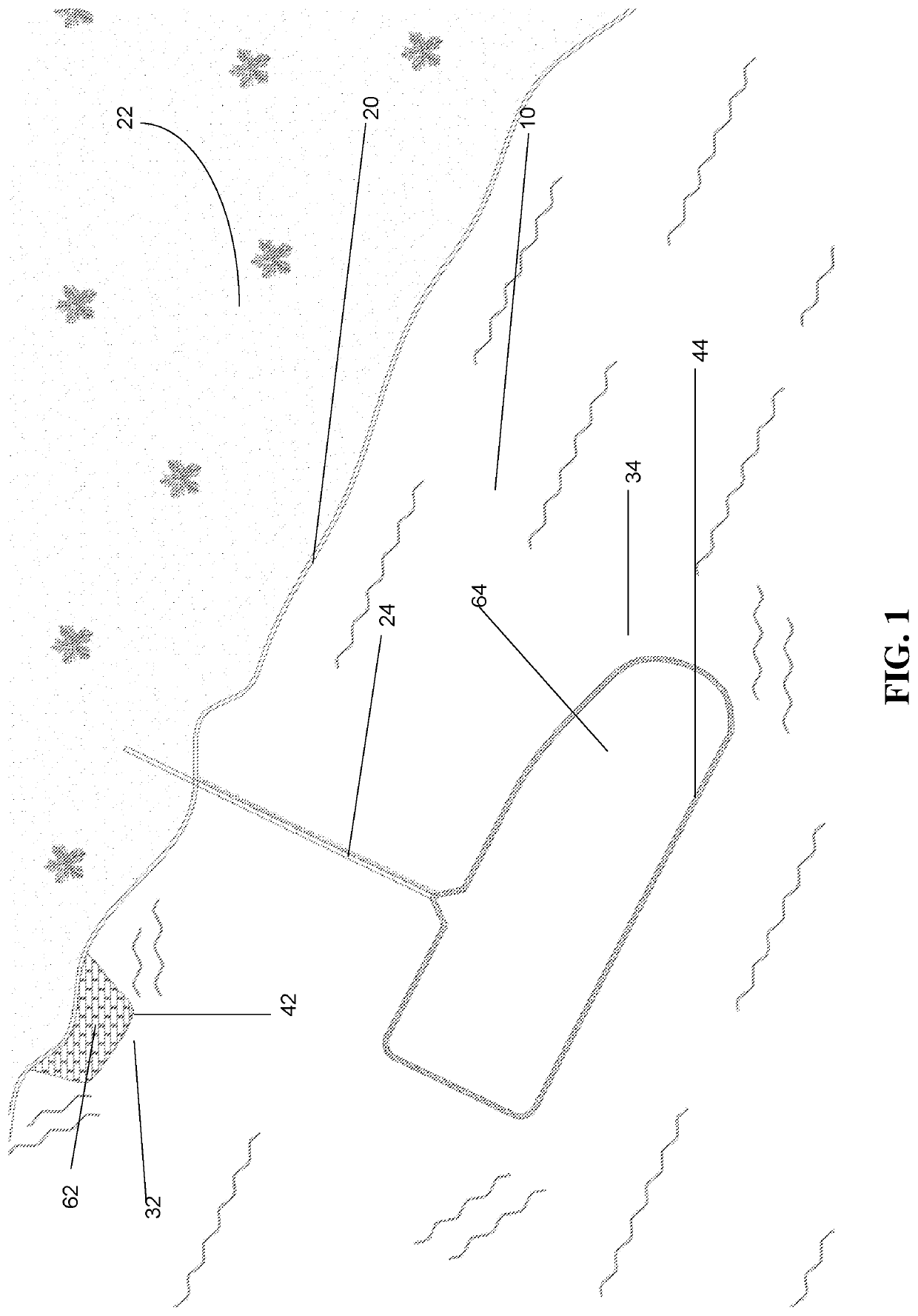
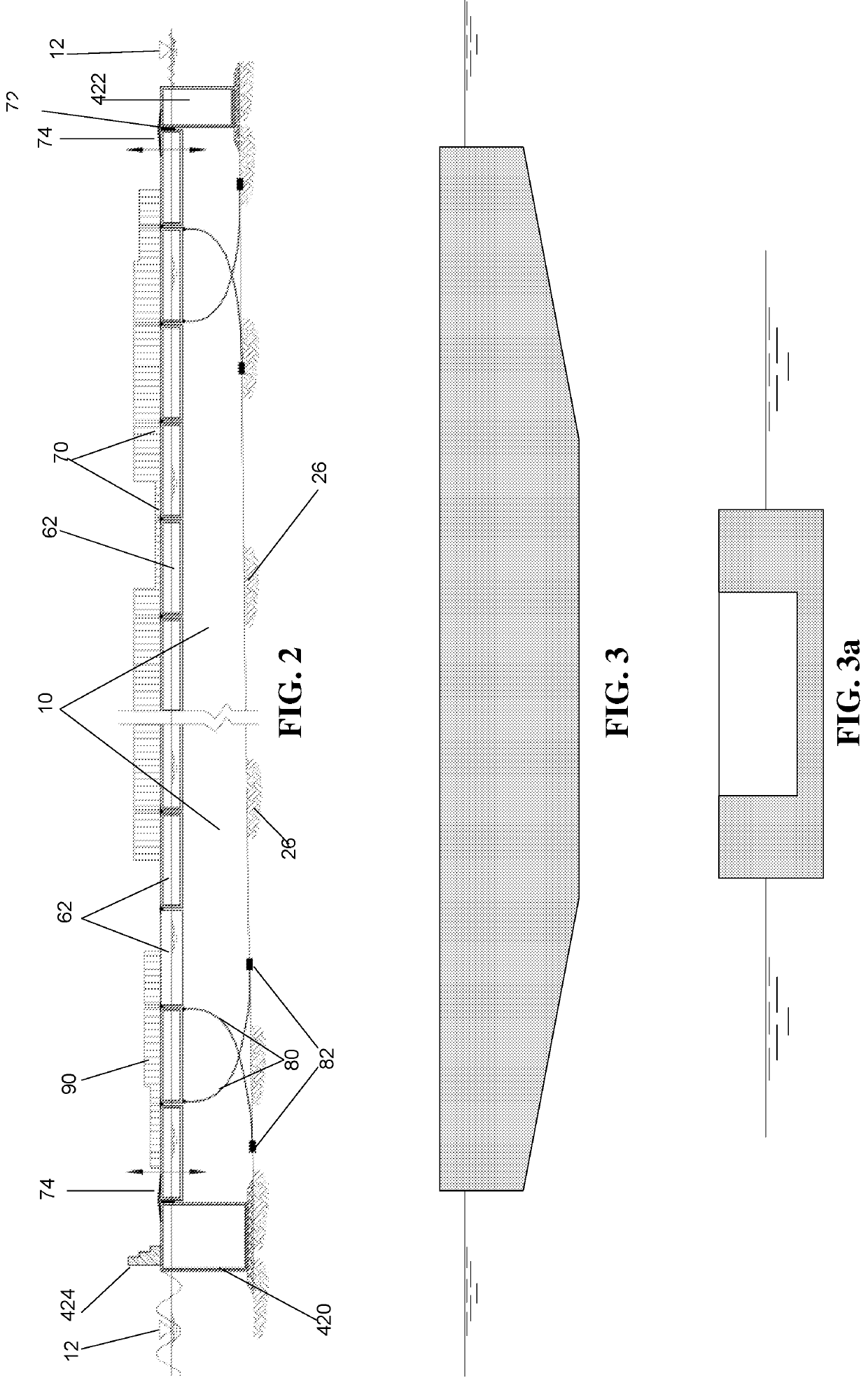
The present invention is a marine construction that can be placed at different distances from shore, on different sea beds, and can perform various tasks and destinations. It can be used for airports, residences, arm bases, power stations, ports, marinas, and other infrastructures.

Problems solved by technology

Reclamation may lead to a great loss of fill material due to waves and currents actions and winds.
However, this type of reclamation requires an outlet for the overflow of water and fine material otherwise, mud can be trapped at or near the corner of the bound.
Some drawbacks of the land reclamation concept derive from the loose nature of the filling material, which could limit the possibilities of stable surfacing the constructed area, or the loading usages allowed thereof.
The main drawback is, of course, the lack of availability of filling materials, especially sand, and the ecologic effect applied both where filling material has been taken near the construction site itself.
The main drawback of all said methods is that they can't provide a marine (in sea) surface that could be stable and balanced, allowing for large scale surface along with significant and versatile load, and without the need for enormous quantities of filling material.
It is to be said that the problem of obtaining filling material is getting more crucial and the amount needed for a reasonable outcome is enormous.
For example, Construction of the Kansai Airport Islands in the vicinity of the Japanese shore was a medium complexity undertaking.

Method used


Image

  • A marine construction and a method for constructing the same
  • A marine construction and a method for constructing the same
  • A marine construction and a method for constructing the same

Examples


Embodiment Construction

[0029]It will be understood that prior art method of marine construction designed to obtain a land like surface in a previous seawater area is divided into two. The first one consists of filling while the other is based on floating elements.

[0030]The prior art methods consisting on filling, are often characterized with a type of outer fixed defining element, to provide strength and stability to the filling material area, while the methods consist of floating elements usually lack such elements.

[0031]The present invention novelty is the combination of external perimeter fixed and stable elements with an inner area floating element.

[0032]Said combination as discussed hereinafter, overcomes the drawbacks of all previous art methods and techniques.

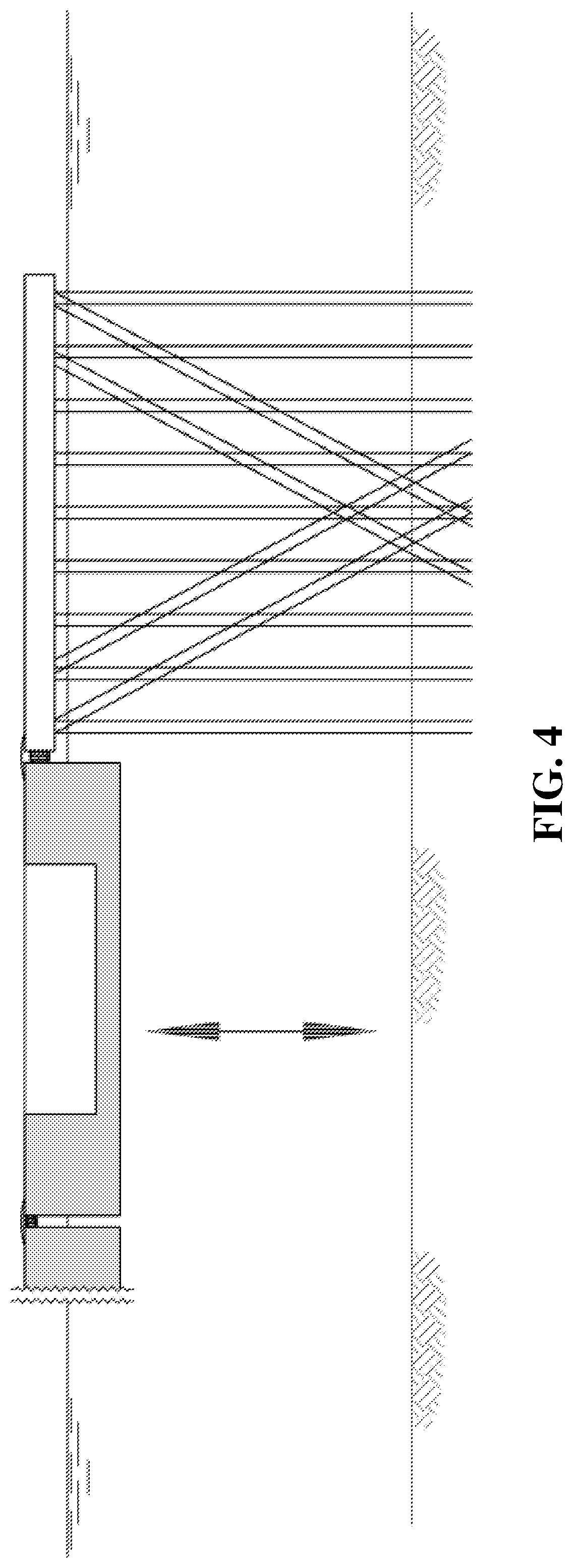
[0033]The external perimeter of the marine construction of the present invention comprises a fixed element lying on the seabed and is located on the defined perimeter of the marine construction. Said fixed element could be a breakwater, a pile...


PUM


Abstract

The present invention provides for a method of marine construction. Said marine construction is based on an external perimeter and inner area and comprises seabed lying elements and floating elements. The marine construction of the present invention comprising fixed elements that are placed on the defined perimeter of said marine construction. Said fixed elements are lying on the seabed. And further comprising floating elements that are placed in the inner area the marine construction, defined by said external perimeter. The marine construction is capable of being deployed at a variety of distances from shore, at a differential nature of sea bed, and to be able to carry out different tasks and destinations, such as but not limited to airport, residency, army base, power station, port, marina, other infrastructures, etc. and any combination thereof.

Description

FIELD OF THE INVENTION[0001]The present invention relates to the construction of artificial surfaces, and more specifically for the construction of marine construction of artificial surfaces, and even more specifically for large scale in-water artificial surfaces.BACKGROUND[0002]As cities, countries and economies expand, the need for land is growing. For many decades, civilizations developed many techniques and methods for enlarging land-like surfaces, on the account of water bodies, especially by expanding into the sea.[0003]Such marine construction includes artificial islands, peninsulas, docks wharves, quays and other port structures, as well as residency, agricultural, transportation and infrastructure plants.[0004]Two basic conceptions are used in such expansion (peninsulas, islands etc.). One is based on floating surfaces and the other land reclamation based on filling marine areas with filling material. Each conception has its drawbacks as will be briefly mentioned hereinafte...

Claims


Application Information

Patent Timeline
IPC IPC(8): B63B35/00B63B21/26B63B21/20B63B39/03B63B5/14
CPCB63B35/00B63B21/26B63B21/20B63B39/03B63B5/14B63B2021/203E02B3/06B63B2035/4473B63B2035/4426E02B3/20B63B3/00E02B17/025Y02A30/00E02B17/021B63B35/38B63B35/53B63B35/44B63B75/00B63B21/50B63B43/06B63B2035/4433E02B17/00
Inventor OSTROVSKY PRESSLER, DANIELADICASTRO, DANOREN, NOA
Owner ISRAEL PORTS DEV & ASSETS CO LTD
Learn More