Device and method for inhibiting biological attachment

A bio-fouling and biological technology, applied in chemical instruments and methods, pollution prevention methods, cleaning methods and utensils, etc., can solve the problems of high maintenance cost, reduced sailing speed, and difficult application, so as to reduce the probability of adhesion, Reduced distribution density, good inhibition effect

Pending Publication Date: 2022-07-26
INST OF PHYSICS - CHINESE ACAD OF SCI +1
View PDF0 Cites 0 Cited by
  • Summary
  • Abstract
  • Description
  • Claims
  • Application Information

AI Technical Summary

Problems solved by technology

Organisms such as barnacles attach to coastal wharves, ship bottoms, submarine cables, etc., often causing great harm. For example, barnacles fixed to the hull greatly reduce the speed of navigation
Therefore, reducing the attachment of barnacles and other organisms in these places or removing the attached barnacles and other organisms has always been an important part of ship and port cleaning, which consumes huge manpower and material resources
At present, the commonly used barnacle cleaning methods mainly include mechanical removal or covering the surface of the hull with special coatings. However, these methods are expensive to use and maintain, and the treatment effect needs to be further improved
In the prior art, there have been attempts to introduce a closed metal wire loop and an alternating current to generate an alternating electromagnetic field to affect the properties of the water body, but the effect on the substances in the water is very weak, and the directly connected circuit has a lot of energy consumption, making it difficult to apply larger

Method used


Image

  • Device and method for inhibiting biological attachment
  • Device and method for inhibiting biological attachment
  • Device and method for inhibiting biological attachment

Examples


Embodiment 1

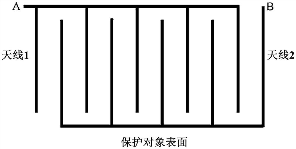
[0056] In the first embodiment, the plane where the antenna array 120 is located is parallel to the surface of the protection object. like image 3 As shown, a cross-type antenna layout is used in this embodiment. Specifically, the antenna array 120 includes two groups of antennas ( image 3 Indicated as antenna 1 and antenna 2), each group of antennas includes a plurality of antenna wires that are parallel and spaced apart from each other, and the antenna wires of the two groups of antennas are alternately crossed to form an interdigitated structure. In application, the A terminals and the B terminals of the two groups of antennas are respectively connected to the radio frequency generator 110 (specifically, the power amplifier 112 ). Changes in the magnitude and direction of the voltage between terminals A and B will generate an alternating electric field between adjacent wires. The alternating electric field can generate an alternating magnetic field and form a local alt...

Embodiment 2

[0059] The difference between the second embodiment and the first embodiment is that in the second embodiment, a relative antenna array layout structure perpendicular to the surface of the protection object is adopted. like Figure 4 As shown, the plane in which the antenna array 120 is located is perpendicular to the surface of the protected object. The antenna array 120 includes two groups of antennas (antenna 1 and antenna 2), each group of antennas includes a plurality of antenna wires parallel and spaced apart from each other, wherein the antenna wires in each group of antennas are perpendicular to the surface of the protected object, and the antenna wires in one group of antennas are perpendicular to the surface of the protected object. Each antenna wire is arranged opposite to the corresponding antenna wire in the other group of antennas in a direction perpendicular to the surface of the protection object, and the adjacent ends of the two opposite antenna wires in the t...

Embodiment 3

[0062] The difference between the third embodiment and the second embodiment is that the antenna layouts that are perpendicular to each other are adopted in the third embodiment. like Figure 5 As shown, in the third embodiment, the plane where the antenna array 120 is located is perpendicular to the surface of the protection object. The antenna array 120 includes two sets of antennas (antenna 1 and antenna 2), and the two sets of antennas are perpendicular to each other, thereby generating electromagnetic waves with different polarization directions. E.g, Figure 5 The antenna wires in the upper and lower directions form the antenna 2, and the antenna wires in the left and right directions form the antenna 1. The propagation directions of the electromagnetic waves generated by the antennas 1 and 2 are parallel to the surface of the protected object, but their polarization directions (ie, the polarization directions) are perpendicular to each other. In applications, the regu...


PUM


Abstract

The invention provides a device and a method for inhibiting biological attachment. The device comprises a radio frequency generator which is used for generating a radio frequency signal with specified frequency and specified intensity; the antenna array is composed of open antenna wires, connected with the radio frequency generator, arranged on the surface, making contact with water, of a protected object and used for emitting the radio frequency signals from the radio frequency generator so as to form radio frequency electromagnetic waves on the surface of the protected object, and therefore attachment of organisms to the surface can be restrained. The radio frequency generator and the antenna array are used for forming the radio frequency electromagnetic waves propagating along the surface on the surface of the protected object (such as a ship body or a marine building) so as to inhibit the organisms from being attached to the surface of the protected object, the method is simple and easy to implement, and the inhibition effect is good.

Description

technical field [0001] The present invention relates to the technical field of surface-attached dirt removal, in particular to a device and method for inhibiting biological attachment. Background technique [0002] Barnacles are arthropods with calcareous shells that cling to seaside rocks. Creatures such as barnacles adhere to coastal docks, ship bottoms, submarine cables, etc., which often cause great harm. For example, barnacles fixed on the hull greatly reduce the sailing speed. Therefore, reducing the attachment of barnacles and other organisms in these places or removing the attached barnacles and other organisms has always been an important part of ship and port cleaning, which consumes huge manpower and material resources. At present, the commonly used barnacle cleaning methods mainly include mechanical removal or special coating on the surface of the hull. However, the use and maintenance costs of these methods are relatively high, and the treatment effect needs to...

Claims


Application Information

Patent Timeline
Patent Type & Authority Applications(China)
IPC IPC(8): H04B1/04A01M29/24B08B17/02
CPCH04B1/04A01M29/24B08B17/02
Inventor 孟庆波张建宏石将建李冬梅
Owner INST OF PHYSICS - CHINESE ACAD OF SCI
Why Eureka
Try Eureka