Optical signal processing apparatus, optical signal processing method and computer program

a technology of optical signal processing and optical signal, applied in the direction of electromagnetic receivers, multi-mode transmission, fibre transmission, etc., can solve the problems of large distortion of signal waveform after transmission, unsuitability of multi-mode fiber for long distance transmission, and further expansion of transmission capacity

Pending Publication Date: 2022-10-13
NIPPON TELEGRAPH & TELEPHONE CORP
View PDF2 Cites 1 Cited by
  • Summary
  • Abstract
  • Description
  • Claims
  • Application Information

AI Technical Summary

Benefits of technology

The present invention provides an efficient way for handling multiple signals in wireless communication systems with reduced impact from the placement of antennas. This allows for faster data transmission and improved performance overall.

Problems solved by technology

The technical problem addressed in this patent text relates to improving the stability and efficient transmission of optical signals through mode division multiplexing optical communication networks. This is achieved by addressing issues related to mode dependence loss and inter-modal dispersion caused by differences in properties of individual cores within a multimode optical fiber. Additionally, the text discusses various techniques for mitigating these challenges, including the use of a learning management system and the selection of optimal weights for the MIMO signal processing.

Method used


Image

  • Optical signal processing apparatus, optical signal processing method and computer program
  • Optical signal processing apparatus, optical signal processing method and computer program
  • Optical signal processing apparatus, optical signal processing method and computer program

Examples


first embodiment

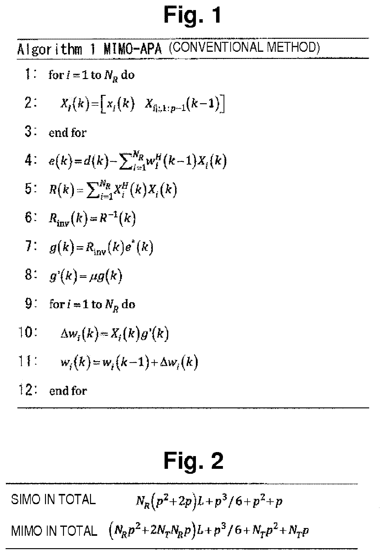
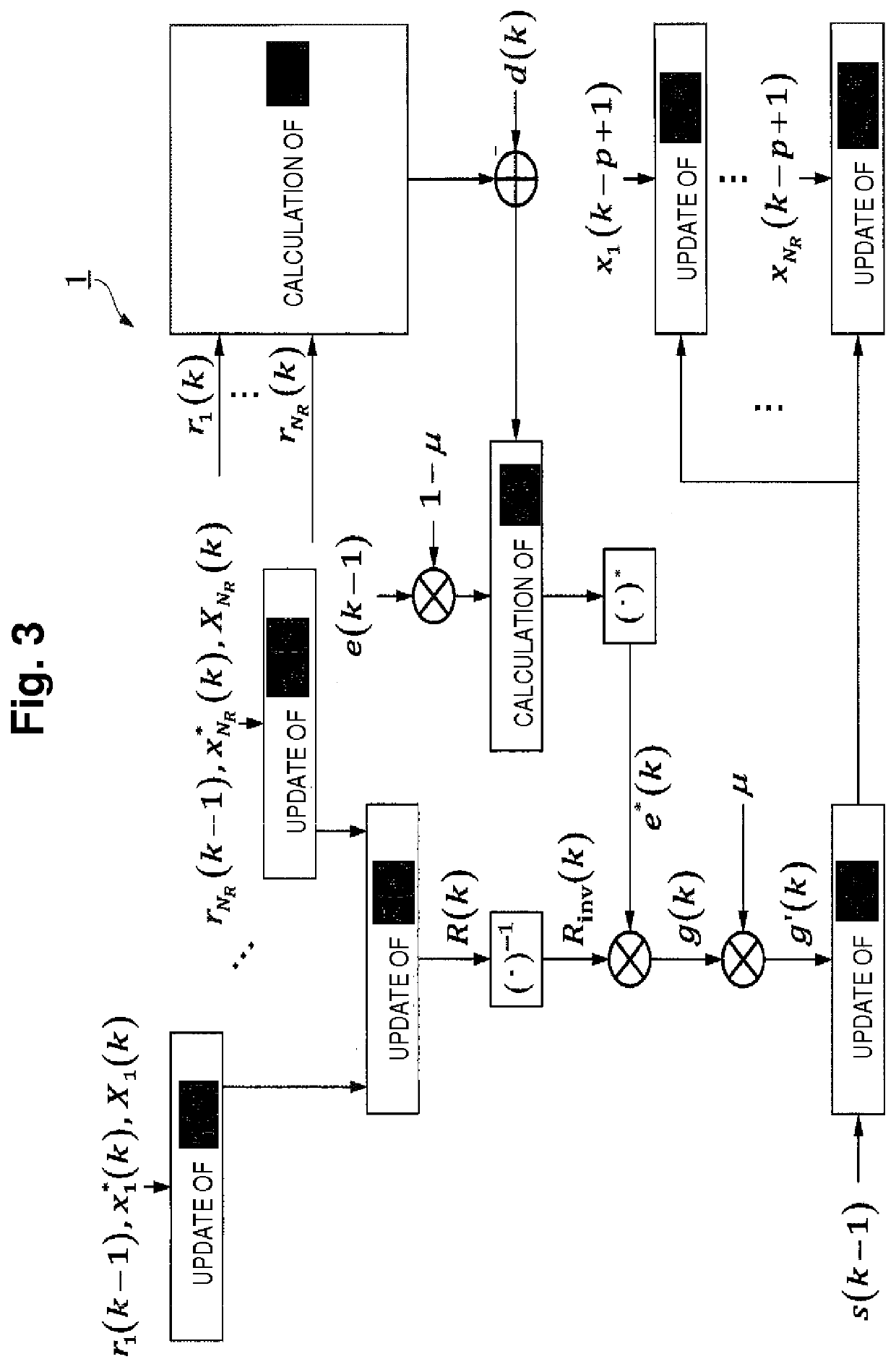
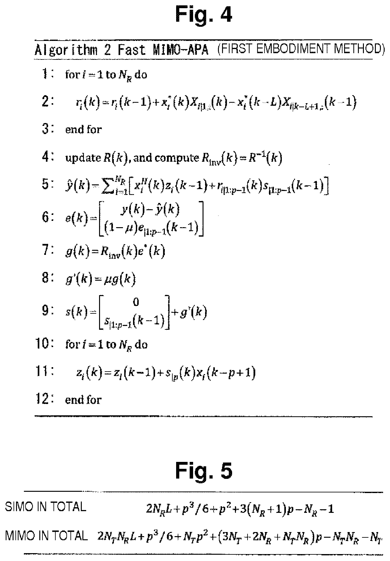
[0055]FIG. 3 is a diagram illustrating a specific example of functional configuration of a signal processing unit 1 provided in an optical signal processing apparatus according to a first embodiment. Further, FIG. 4 illustrates a specific example of algorithm of a high-speed MIMO type affine projection method (Fast MIMO-APA) that can be realized by the functional configuration illustrated in FIG. 3. In the high-speed MIMO type affine projection method, a correlation vector ri(k), a smoothing prefilter vector s(k), and a deformation filter vector z(k), which are auxiliary variables, are introduced in the conventional sub-filter style MIMO type affine projection method. Performing the same calculation as the sub-filter style MIMO type affine projection method after the introduction of the auxiliary variables can mainly reduce the frequency of complex multiplication in the calculation of respective variables.

[0056]Hereinafter, the definition and meaning each auxiliary variable will be...

second embodiment

[0063]FIG. 6 is a diagram illustrating a specific example of functional configuration of a signal processing unit 1a provided in an optical signal processing apparatus according to a second embodiment. Further, FIG. 7 illustrates an algorithm of high-speed MIMO type affine projection method (Fast MIMO-APA) that can be realized by the signal processing unit 1a illustrated in FIG. 6. The high-speed MIMO type affine projection method according to the second embodiment intends to remove loop processing from the high-speed MIMO type affine projection method in the first embodiment and reduce the number of accesses to a memory, thereby simplifying the operation.

[0064]Specifically, the following two points are changed for the high-speed MIMO type affine projection method in the first embodiment.

[0065](1) For each variable, what has been defined for each stream (input signal of each mode) is defined in all streams by batch (deletion of loop processing).

[0066](2) Input data-hold matrix X˜(k)...


PUM


Abstract

An optical signal processing apparatus of an embodiment is an optical signal processing apparatus for separating and detecting an optical signal transmitted in a mode division multiplexing optical communication method by signal processing based on a multi-input multi-output (MIMO)-type linear filter. The device includes a signal processing unit configured to estimate weighting factors of the MIMO-type linear filter by sequential calculation based on an affine projection method. In the sequential calculation of the signal processing device, an output signal by the sequential calculation is expressed by a correlation vector indicating a correlation between the plurality of input signals, a smoothing prefilter vector indicating, of smoothing prefilter factors indicating a relationship between the weighting factors at current time and input signals from a first time being a past predetermined time to the current time, smoothing prefilter factors corresponding to each time from the first time to a second time that corresponds to an affine projection order in the affine projection method, and input signals from the first time to the second time.

Description


Claims


Application Information

Patent Timeline
Owner NIPPON TELEGRAPH & TELEPHONE CORP
Why Eureka
Try Eureka