Loudspeaker array with multiple drivers

a loudspeaker array and driver technology, applied in the field of loudspeakers, can solve the problems of reducing the output of the woofer, affecting the performance of the woofer, and affecting the quality of the woofer, so as to reduce resonance and irregularities in the frequency response, reduce the resonance and the effect of irregularities

Active Publication Date: 2022-10-13
GP ACOUSTICS INT
View PDF0 Cites 0 Cited by
  • Summary
  • Abstract
  • Description
  • Claims
  • Application Information

AI Technical Summary

Benefits of technology

[0009]Providing an acoustically open rear (or “open back”) to the unitary assembly (which might be achieved by removing the shield 16 in the arrangement of FIG. 1) allows the sound from the back of the midrange driver to radiate into the woofer front cavity and then through the annular woofer aperture into free space. The far-field sound pressure is therefore a combination of the front and the back radiation of the midrange driver leading to an acoustical short-circuit and a corresponding high-pass acoustic response (as shown in FIGS. 4a and 4b). A less obvious result of this arrangement is that the large dip in the power response is removed allowing a greatly improved response.
[0010]There may be acoustically absorbent material located in the woofer front cavity between the rear of the unitary assembly and the front of the at least one low frequency driver. This material should not fill the woofer front cavity, but instead should be positioned and configured so as to leave a clear path for acoustic waves from the low frequency driver(s) to travel towards a listener in front of the loudspeaker array. the acoustically absorbent material preferably extends so as substantially to separate the rear of the midrange driver from the low frequency driver. The acoustically absorbent material may form an enclosure surrounding the rear of the unitary assembly. The acoustically absorbent material is preferably porous or fibrous (i.e. not airtight), and may be a material such as foam (open cell or reticulated cell), felt or wadding. The acoustically absorbent material reduces resonances and irregularities in the frequency response, and increases the low frequency output of the midrange driver, reducing the effect of the acoustic short circuit between front and back of the driver.
[0012]There may be a woofer aperture extending around the unitary assembly through which low frequency acoustic waves from the low frequency driver radiate forwardly of the speaker system, in which acoustically absorbent material may be provided, located at or within the woofer aperture. Preferably this acoustically absorbent material does not fill the woofer aperture, so that the woofer can maintain a certain amount of flow. There may be a baffle provided around the unitary assembly, extending generally rearwardly of it and configured to prevent or reduce acoustic diffraction. Additional foam or other absorbent material at the periphery of the woofer cavity and / or the use of a curved baffle may reduce the diffraction (spreading of the acoustic waves as they pass through the woofer aperture) providing a smoother response and less angular variation at higher frequencies. There may be extending over all or part of the woofer aperture.

Problems solved by technology

Such a configuration means that there is a large woofer annulus, which requires a large and heavy coil to drive it; this is expensive to manufacture and operate.
A common problem with the arrangement shown in FIG. 1 is that the woofer front cavity 10 resonates at frequencies determined by the shape and size of the cavity.
Although these cavity resonances can be damped by incorporating sufficient acoustically absorbent material in the woofer cavity, the resulting acoustic resistance and turbulence due to high air velocity due to the constricted path strongly reduces the woofer output and the low-frequency output limiting the system efficiency.

Method used


Image

  • Loudspeaker array with multiple drivers
  • Loudspeaker array with multiple drivers
  • Loudspeaker array with multiple drivers

Examples


Embodiment Construction

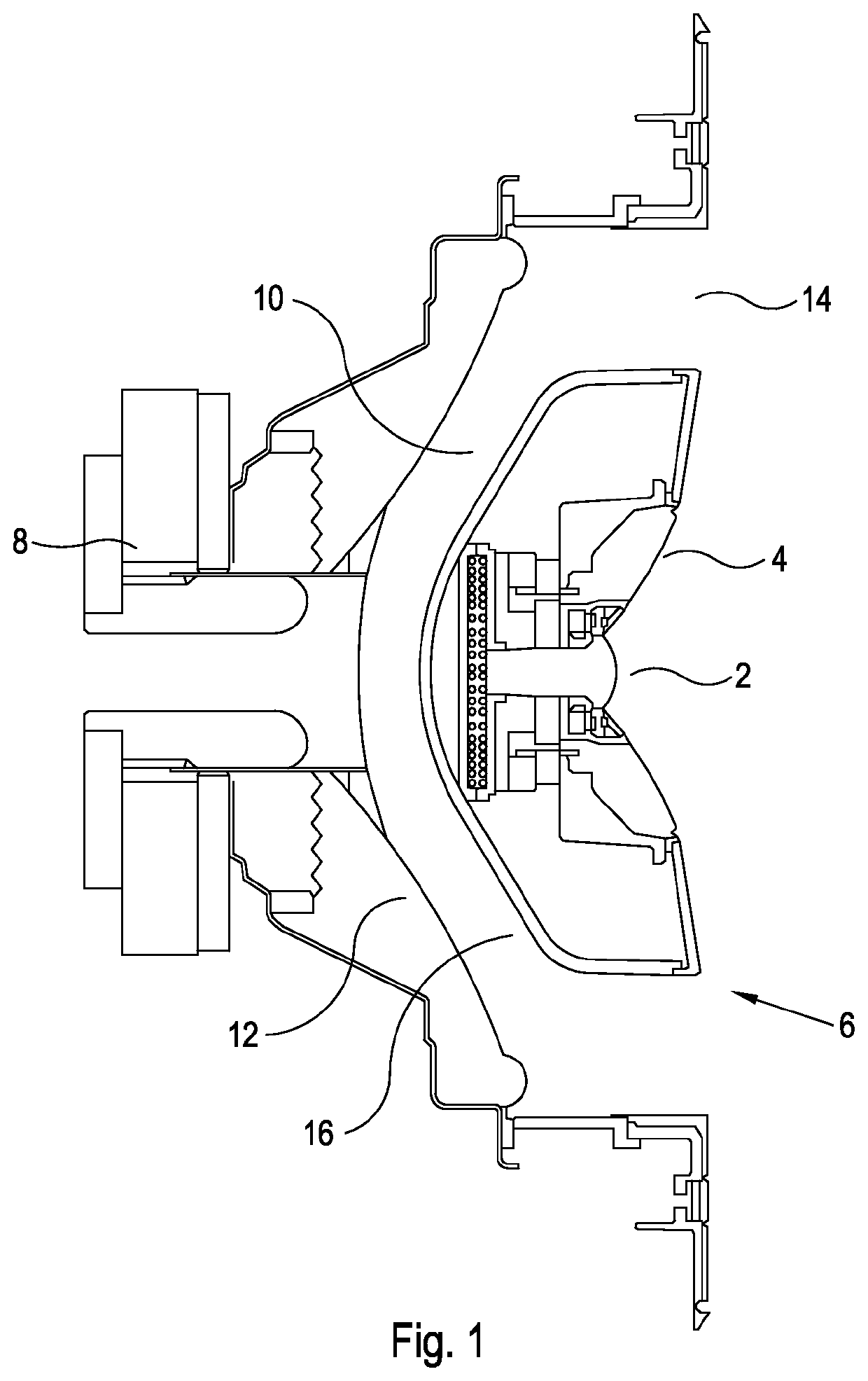
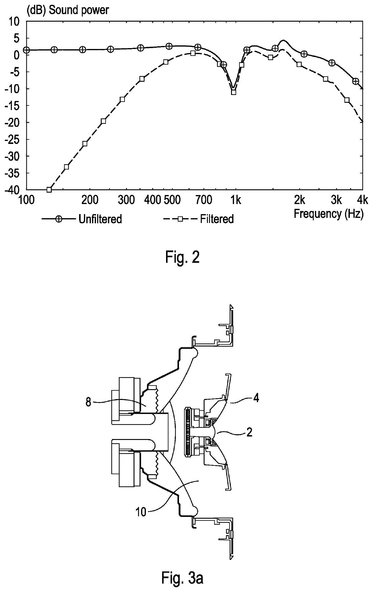
[0022]FIG. 1 shows a prior art loudspeaker array which is described above. FIG. 2 shows the theoretical sound power response of the conventional loudspeaker array of FIG. 1, and is also explained above.

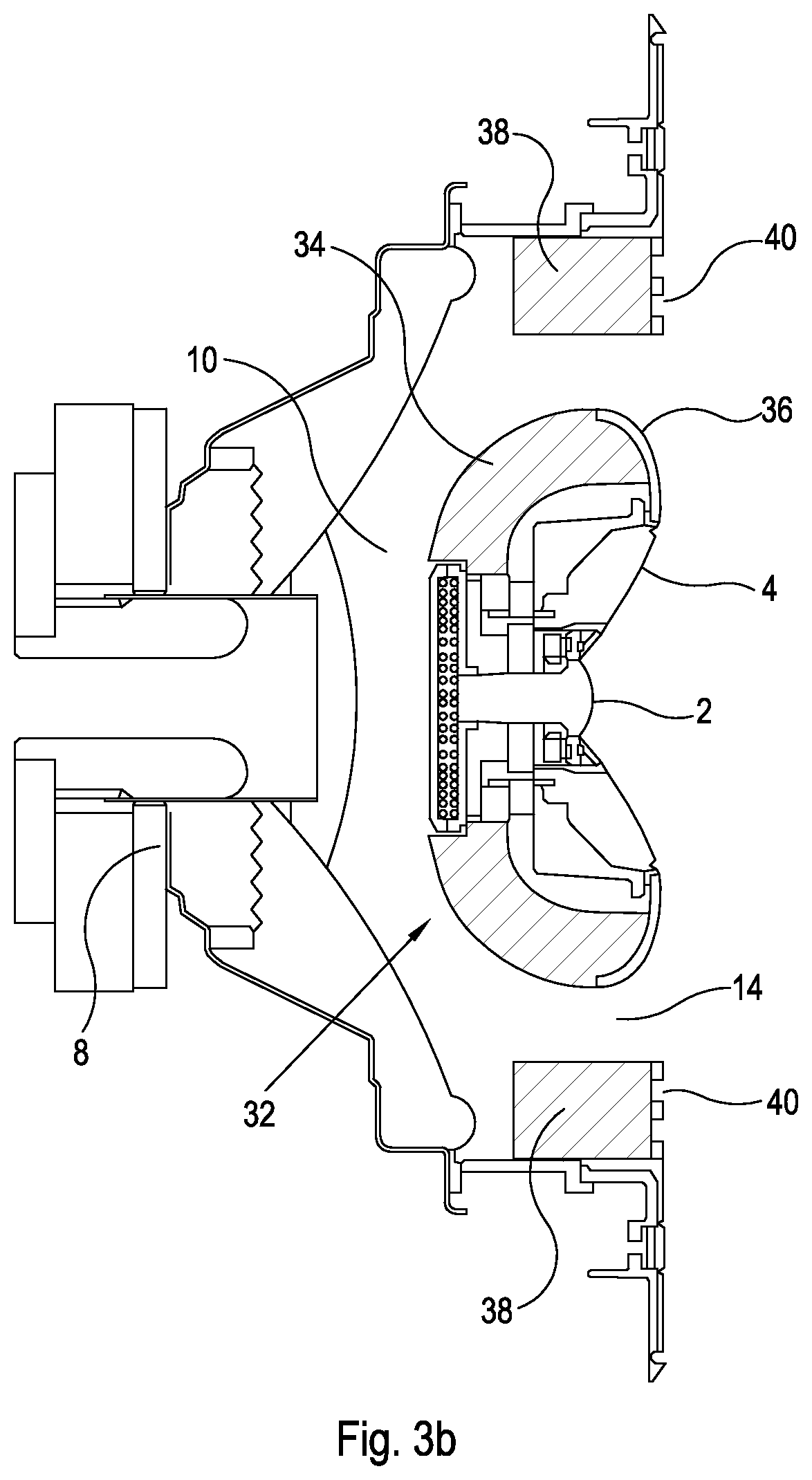
[0023]FIGS. 3a and 3b show two embodiments of loudspeaker arrays in accordance with the present invention; elements of these embodiments which are substantially the same as those in the loudspeaker array of FIG. 1 bear the same reference numerals as the elements in FIG. 1. In these drawings the front, as that term is applied herein to any element of the loudspeaker array, and the forward direction, as that term is applied herein to any direction, mean the right hand side of the drawing, and the terms back, rear and rearwardly mean the left hand side of the drawing. The axis referred to herein runs horizontally, left to right in the drawings. As in FIG. 1, the tweeter 2 is located on the left / right horizontal axis with an annular midrange driver 4 arranged concentrically around the twe...


PUM


Abstract

The present invention relates to a loudspeaker array comprising: a high frequency driver and a midrange driver forming a unitary assembly and configured to direct acoustic waves towards a listener in front of the loudspeaker array along an axis in a forward direction; at least one low frequency driver located generally rearwardly of the unitary assembly, and a woofer volume extending along and perpendicular to the axis between the at least one low frequency driver and the unitary assembly, in which the rear of the unitary assembly is configured and acoustically open so as to allow sound from the rear of the midrange driver to radiate rearwardly into the woofer volume.

Description

CROSS REFERENCE TO RELATED APPLICATION[0001]This application claims priority to and benefits of GB Patent Application No. 2105018.2, filed Apr. 8, 2021, the content of which is hereby incorporated by reference in its entirety.FIELD OF THE INVENTION[0002]The present invention relates to the field of loudspeakers, and especially relates to loudspeakers consisting of an enclosure containing a plurality of acoustic drivers, and particularly but not exclusively to loudspeakers in which two or more drivers are arranged coaxially.BACKGROUND ART[0003]A simple loudspeaker typically has a voice coil comprising a conductor through which a current may be passed, placed within a magnet assembly so that when current is passed through the voice coil an electromagnetic driving force is produced. This in turn drives a driven body, such as a diaphragm. Conventionally, this vibrates along the loudspeaker axis (i.e. the axis which passes from a front to a rear of the loudspeaker and which is substantia...

Claims


Application Information

Patent Timeline
Patent Type & Authority Applications(United States)
IPC IPC(8): H04R1/24H04R1/28H04R1/02H04R7/12H04R1/40
CPCH04R1/24H04R1/288H04R1/023H04R7/12H04R1/403H04R1/025H04R9/06H04R9/02H04R9/063
Inventor DEGRAEVE, SEBASTIEN
Owner GP ACOUSTICS INT
Why Eureka
Try Eureka