Stowable Power Generator Device

a power generator and stowable technology, applied in the field of stowable energy sources, can solve the problems of affecting the operation of the generator,

Pending Publication Date: 2022-11-03
WOODS HOLE OCEANOGRAPHIC INSTITUTION
View PDF0 Cites 0 Cited by
  • Summary
  • Abstract
  • Description
  • Claims
  • Application Information

AI Technical Summary

Benefits of technology

[0011]Here is described a generator device with a stowable generating unit carried by collapsible support structure, enabling the stowage of the generating unit, protecting it from the environment, and providing a pleasing view when stowed.
[0014]Such a collapsible generator can be more readily transported in a compact state and then quickly deployed when needed. Another application could be in sailboats, allowing for a larger device for more power generation when deployed, but capable of being stowed away when higher performance is required for sailing. In addition to having applicability in “terrestrial” and more consumer-facing markets, this concept could be a useful deployment mechanism for oceanographic sensors as well.

Problems solved by technology

A common problem with these energy sources is that they are not present at all times, meaning a generator may be unused for a portion of time.
However, the configuration is complex and only provides a solution for the tower assembly, not the windmill blades, which apparently must be mounted manually.
U.S. Publication No. 2011 / 0042958 A1 describes a collapsible wind turbine for ease of maintenance and transportation; however, the blades of the turbine remain exposed to the environment when the turbine is in the collapsed configuration, with each blade still presenting a large frontal area that would catch the wind and make moving the collapsed turbine more difficult.
Furthermore, the turbine blades remain visible when not in use, and may still be considered an eye-sore or an otherwise unwanted view.
However, unlike HATs whose pitch can be locked in high winds, VATs cannot be locked and have potential to become damaged in high winds.

Method used


Image

  • Stowable Power Generator Device
  • Stowable Power Generator Device
  • Stowable Power Generator Device

Examples


Embodiment Construction

Overview

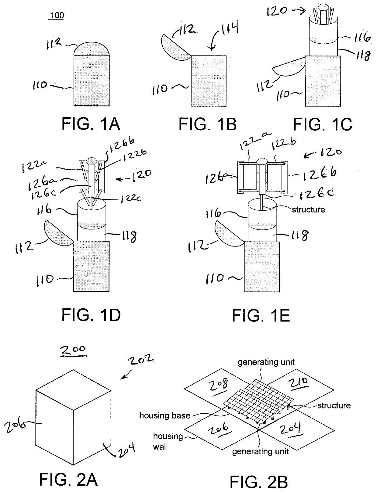
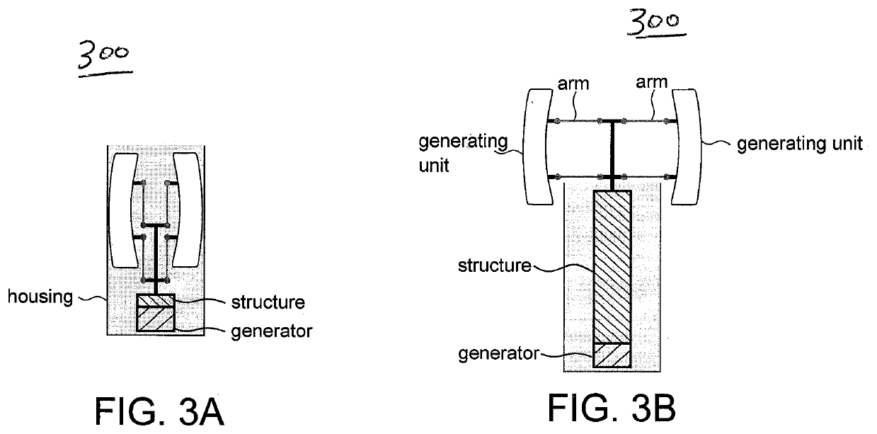
[0027]The present disclosure describes a generator device having a housing, a support structure typically including at least one arm, and an energy generating unit which may include a generator and / or an energy storage device such as a battery. The generator device may be accomplished in several ways with different embodiments. Device 100, FIGS. 1A-1E, has a housing 110 defining a storage compartment 114, a closure element 112 such as a pivoting lid, and a stowable structure 120 including arms 122a, 122b, 122c and generating units 126a, 126b, 126c such as wind turbine blades that fit within the storage compartment 114 of housing 110. Generating units 126a-c can collapse into and extend out of the housing 110, forming a collapsible and stowable device that is portable.

[0028]In a first stage extension configuration, FIG. 1C, an optional solar array 116 mounted on support cylinder 118 has extended into an exposed condition while the wind turbine structure 120 is not yet extende...


PUM


Abstract

A stowable generator device including a housing defining at least one storage chamber having an opening. A closure element is configured to selectively cover and uncover the opening. Support structure is disposed within the storage chamber in a collapsed position and is selectively extendable through the opening into an expanded position when the closure element is moved away from the opening. At least one energy generating unit is connected to the support structure. The support structure and the generating unit are configured to reversibly stow inside the housing in the collapsed position.

Description

CROSS-REFERENCE(S) TO RELATED APPLICATION(S)[0001]This application claims priority to U.S. Provisional Application No. 63 / 183,248 filed 3 May 2021. The entire contents of the above-mentioned application are incorporated herein by reference.STATEMENT REGARDING GOVERNMENT LICENSE RIGHTS[0002]The invention described herein was made with U.S. government support under Award No. N00024-10-D-6318 / DO#N0002420F8712, UW Subaward No. UWSC12118 awarded by the Defense Advanced Research Projects Agency (“DARPA”) of the U.S. Department of Defense. The U.S. Government has certain rights in the invention.FIELD OF THE DISCLOSURE[0003]This invention relates to stowable energy sources, particularly wind, hydroelectric, and solar energy collectors that may be stored within a protective housing and selectively deployed.BACKGROUND[0004]Wind, hydroelectric, and solar power are three promising renewable energy resources. They are abundant, inexhaustible, widely distributed, and clean. Because of these attri...

Claims


Application Information

Patent Timeline
Patent Type & Authority Applications(United States)
IPC IPC(8): E04B1/344F03D13/20H02S10/12H02S30/20B65D85/68B65D88/12
CPCE04B1/344F03D13/20H02S10/12H02S30/20B65D85/68B65D88/121F05B2240/91Y02E10/74F05B2240/915F05B2240/142F05B2240/211H02S20/30
Inventor LITTLEFIELD, ROBINKAELI, JEFFREY
Owner WOODS HOLE OCEANOGRAPHIC INSTITUTION
Why Eureka
Try Eureka