Joining arrangement having a receiving means and a ball joint

Pending Publication Date: 2022-11-03
HELLA GMBH & CO KG
View PDF0 Cites 0 Cited by
  • Summary
  • Abstract
  • Description
  • Claims
  • Application Information

AI Technical Summary

Benefits of technology

The invention allows for compensation of dimensional tolerances during assembly of a joining arrangement by ensuring the joint socket can move within the receiver. The locking arms guide the joint socket and only when the joint pin is inserted, a clamping connection is established between the joint socket and the receiver. This fixed position of the joint enables precise positioning of the assembly (e.g. a light module) mounted on the ball joint. The joint socket also has a positioning rib to prevent rotation during assembly.

Problems solved by technology

In practice, during the assembly of such joining arrangements with a ball joint fixed in a receiver on the support frame side, the problem arises that due to manufacturing and / or assembly tolerances, the position of the receiver relative to other components of the lighting device is not always dimensionally accurate.
In particular, if the assembly to be fixed, for example, a light module, has to be attached to the support frame via a plurality of receiver, such tolerances lead to major assembly difficulties or to rejection of components.

Method used


Image

  • Joining arrangement having a receiving means and a ball joint
  • Joining arrangement having a receiving means and a ball joint
  • Joining arrangement having a receiving means and a ball joint

Examples


Embodiment Construction

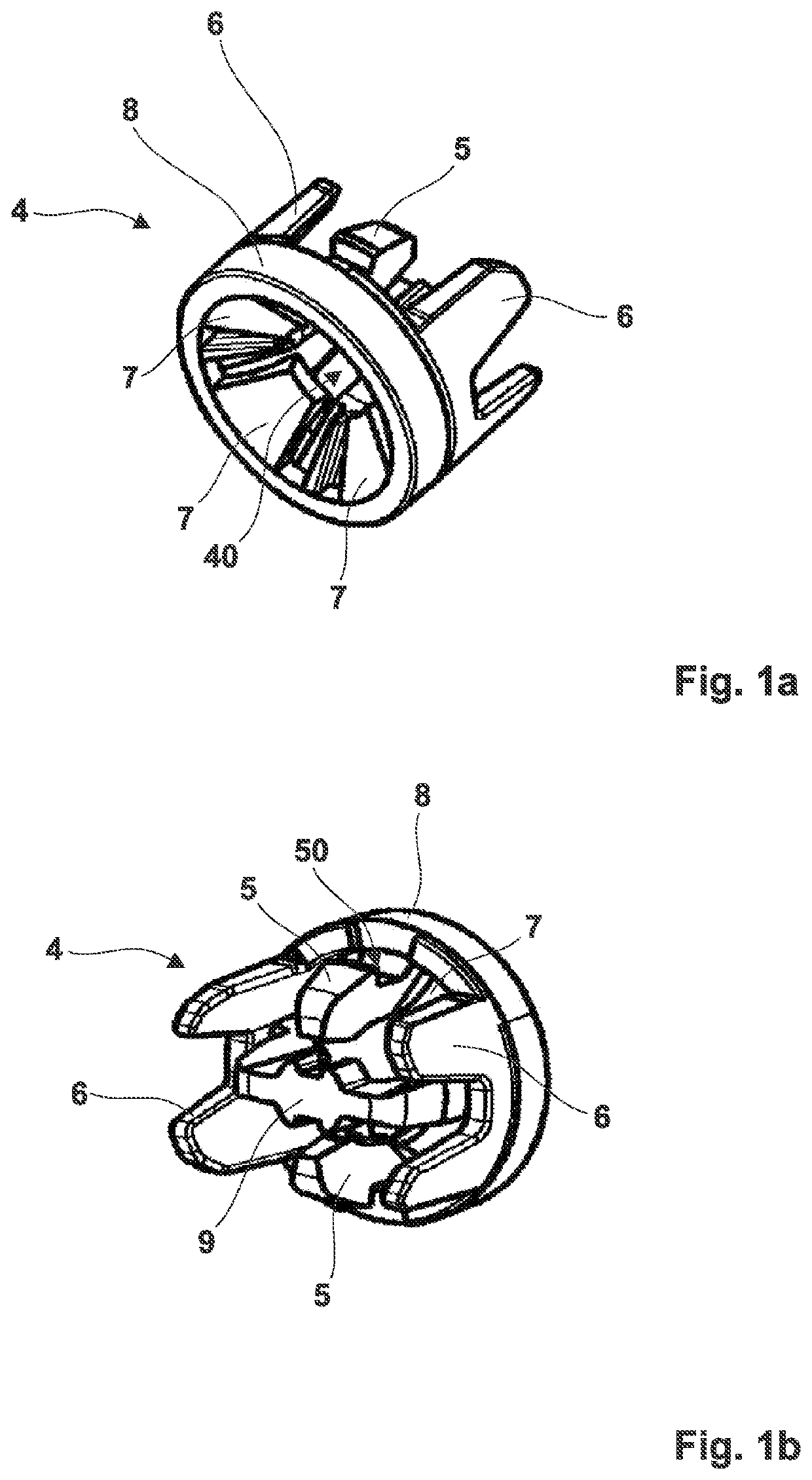
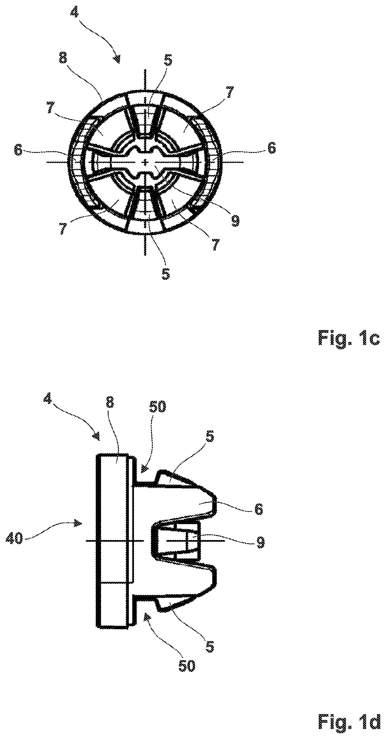
[0021]FIGS. 1a to 1d show perspective views of a joint socket 4 of a ball joint of the invention, which comprises annular outer sleeve 8 from which four resilient tongues 7 extend in the direction of joint ball receiving opening 40, wherein two locking arms 5, two U-shaped positioning ribs 6, and support web 9 project in the rearward direction from outer sleeve 8. Joint socket 4 is formed of, for example, of a thermoplastic, for instance, polyoxymethylene (POM), and is advantageously manufactured by means of an injection molding process.

[0022]The two locking arms 5 each have a notch 50 on the outside for receiving a guide element of a receiver, and a concavely curved surface section on the inside, which serves to form a socket bearing for a joint ball. The socket bearing is further formed by the surface sections of support web 9, which are concavely curved on the inside. To assemble the ball joint, a joint pin with a joint ball is inserted into joint ball receiving opening 40, where...


PUM


Abstract

A joining arrangement having a receiver and a ball joint, wherein the ball joint comprises a joint pin with a joint ball and comprises a joint socket for receiving the joint ball, and wherein the ball joint is spread open resiliently into the receiver. According to the invention, the receiver has a guide element with a guide region which extends in a guide direction, wherein the joint socket is, by means of at least two locking arms, spread open resiliently into the guide element in a preselectable setpoint position within the guide region.

Description

[0001]This nonprovisional application is a continuation of International Application No. PCT / EP2021 / 050120, which was filed on Jan. 6, 2021, and which claims priority to German Patent Application No. 10 2020 100 918.6, which was filed in Germany on Jan. 16, 2020, and which are both herein incorporated by reference.BACKGROUND OF THE INVENTIONField of the Invention[0002]The present invention relates to a joining arrangement having a receiver and a ball joint, wherein the ball joint comprises a joint pin with a joint ball and comprises a joint socket for receiving the joint ball, and wherein the ball joint is spread open resiliently into the receiver. Furthermore, the invention relates to a ball joint for use in such a joining arrangement and to a method for mounting a light module on a support frame of a vehicle lighting device.Description of the Background Art[0003]A joint in which the joint head has a spherical shape is referred to as a ball joint, wherein the counterpart, which enc...

Claims


Application Information

Patent Timeline
IPC IPC(8): F16C11/06
CPCF16C11/0623F16C11/0695F16C11/0657
Inventor JAPS, EDUARD
Owner HELLA GMBH & CO KG
Why Eureka
Try Eureka