
Aerosol Generation Device and Heating Chamber Therefor

Pending Publication Date: 2022-11-17
JT INT SA
View PDF0 Cites 0 Cited by
  • Summary
  • Abstract
  • Description
  • Claims
  • Application Information

AI Technical Summary

Benefits of technology

The patent text describes a device used in the production of aerosol substrates, which can heat and compress the substrate to maintain it in place during the heating process. To improve grip on the substrate, the device uses multiple gripping elements with larger restriction diameters than the thermal engagement elements, which are positioned in a more rigid region of the substrate carrier. This ensures that the substrate carrier can deform less easily during the heating process. The gripping elements are also designed to minimize heat transfer to the substrate carrier and provide sufficient grip without adding too much resistance or deformation. The thermal engagement elements have a flattened profile that maximizes surface area in contact with the substrate carrier. The technical effects of this device include improved gripping of the substrate carrier, reduced deformation during the heating process, and improved heat transfer efficiency.

Problems solved by technology

It has been found that as the aerosol substrate is heated, the aerosol substrate shrinks away from the thermal engagement elements and the compression force to maintain the substrate carrier in the heating chamber and prevent it falling out is no longer optimal.

Method used


Image

  • Aerosol Generation Device and Heating Chamber Therefor
  • Aerosol Generation Device and Heating Chamber Therefor
  • Aerosol Generation Device and Heating Chamber Therefor

Examples


Embodiment Construction

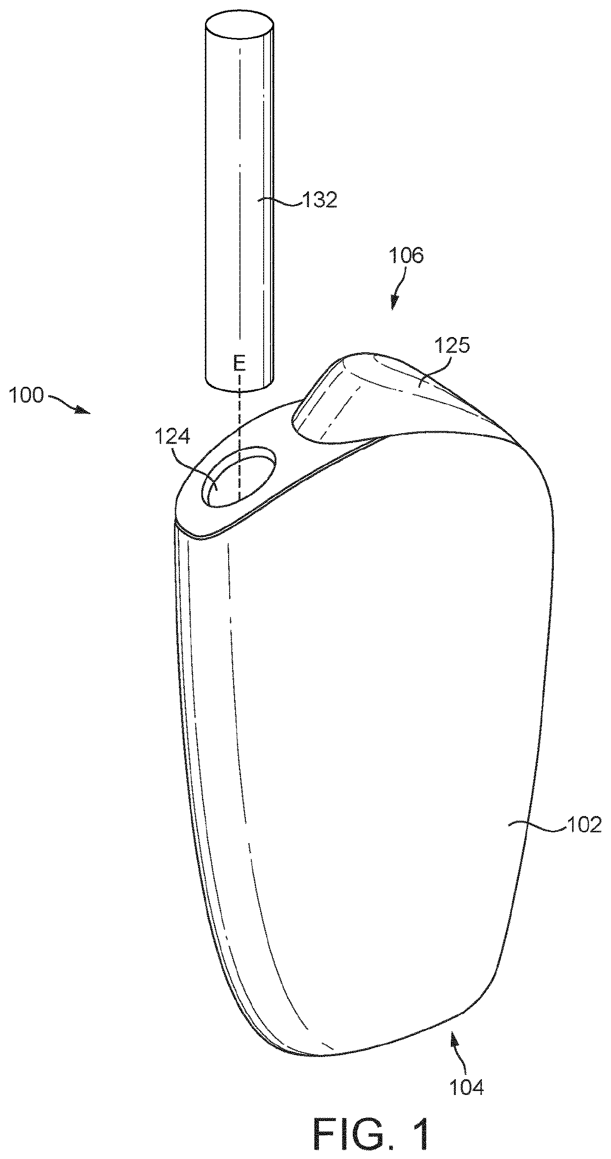
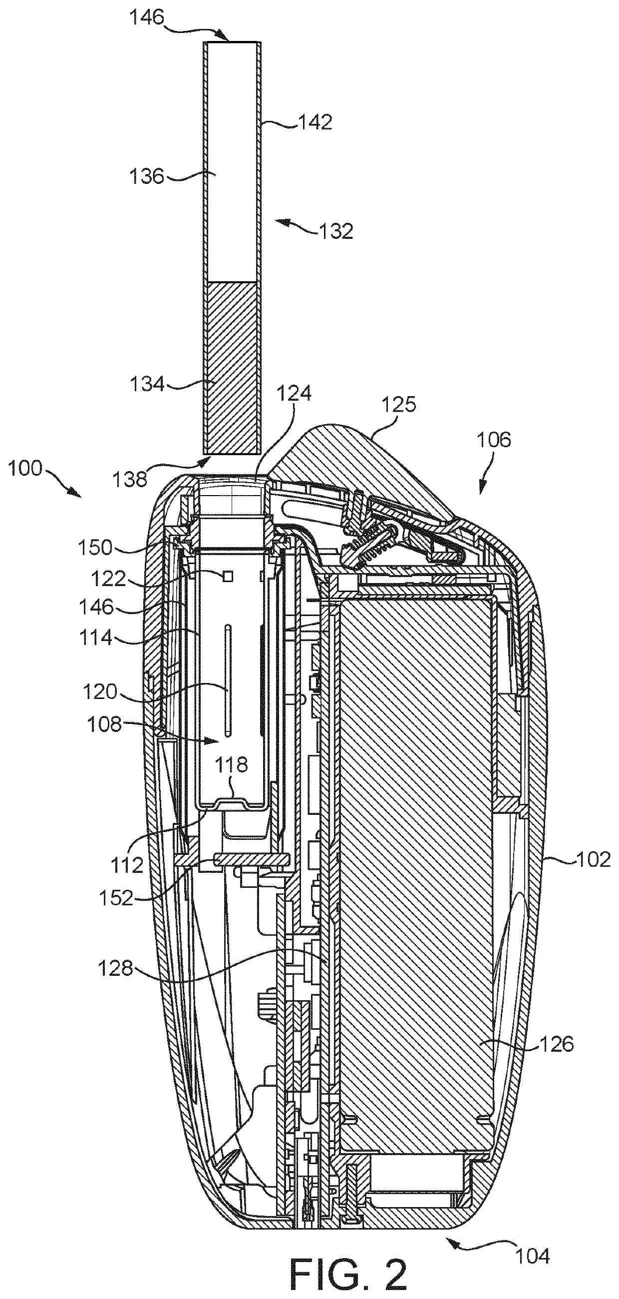
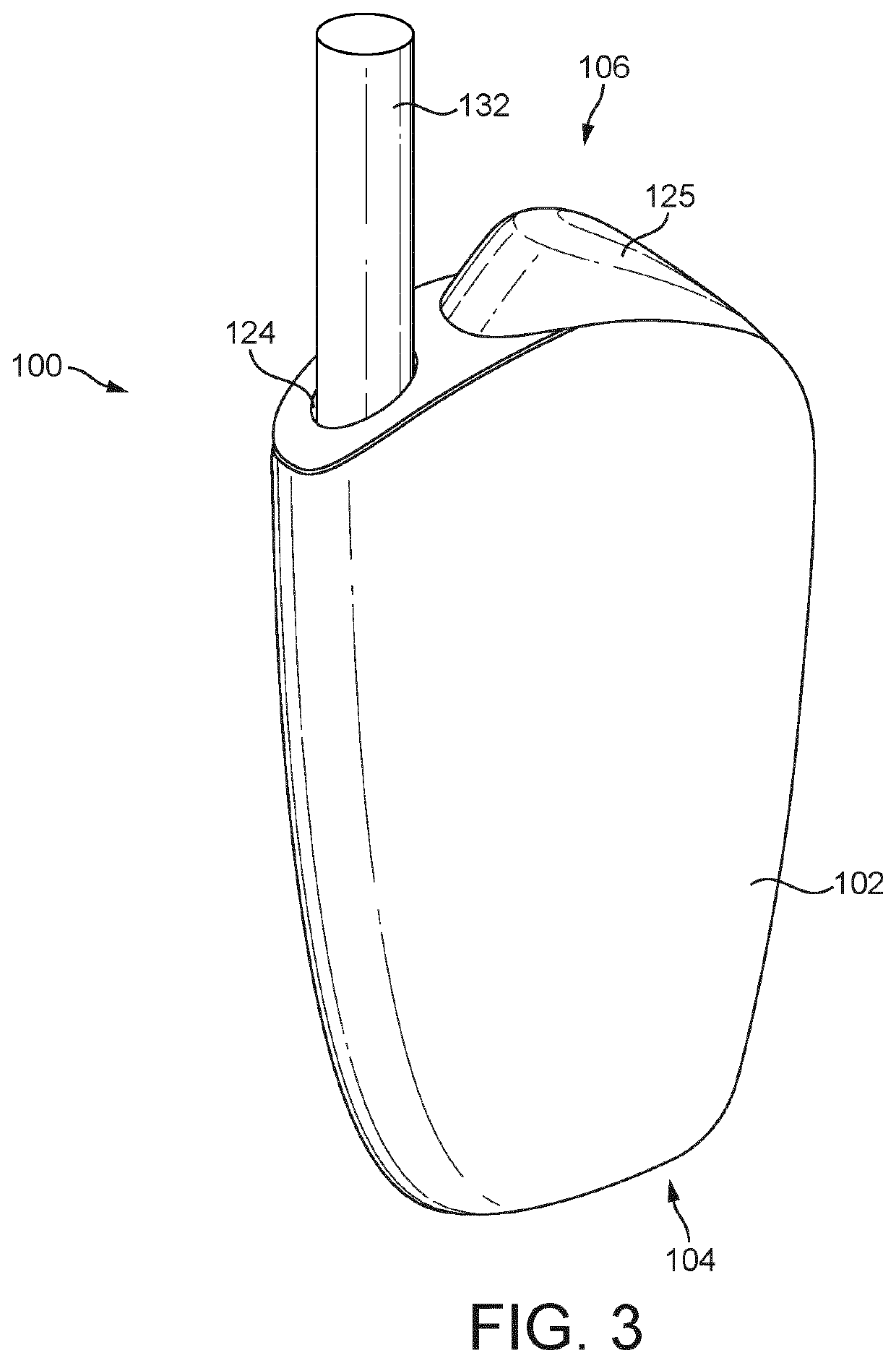
[0087]Referring to FIGS. 1 to 4, an aerosol generation device 100 is provided. The aerosol generation device 100 is arranged to receive a substrate carrier 132 comprising an aerosol substrate 134 and is configured to heat the aerosol substrate 134 inserted therein to form an aerosol for inhalation by a user. The aerosol generation device 100 may be described as a personal inhaler device, an electronic cigarette (or e-cigarette), vaporiser or vaping device. In the illustrated example, the aerosol generation device 100 is a Heat not Burn (HnB) device. However, aerosol generation devices 100 that are envisaged in the disclosure more generally heat or agitate an aerosolisable substance to generate an aerosol for inhalation, as opposed to burning tobacco as in conventional tobacco products.

[0088]Referring to FIG. 1, the aerosol generation device 100 comprises an outer casing 102 housing various components of the aerosol generation device 100. The outer casing 102 can be formed of any sui...


PUM


Abstract

A heating chamber for an aerosol generation device includes an open first end through which a substrate carrier including aerosol substrate is insertable along a length of the heating chamber. The heating chamber further includes a side wall, and a plurality of thermal engagement elements for contacting and providing heat to the substrate carrier. The heating chamber further includes a plurality of gripping elements, spaced apart from the thermal engagement elements along a length of the side wall, each gripping element extending inwardly from the interior surface of the side wall into the interior volume at a different location around the side wall, wherein the gripping elements are located closer to the open first end than the thermal engagement elements.

Description

FIELD OF THE DISCLOSURE[0001]The present disclosure relates to an aerosol generation device and to a heating chamber therefor. The disclosure is particularly applicable to a portable aerosol generation device, which may be self-contained and low temperature. Such devices may heat, rather than burn, tobacco or other suitable materials by conduction, convection, and / or radiation, to generate an aerosol for inhalation.Background to the Disclosure[0002]The popularity and use of reduced-risk or modified-risk devices (also known as vaporisers) has grown rapidly in the past few years as an aid to assist habitual smokers wishing to quit smoking traditional tobacco products such as cigarettes, cigars, cigarillos, and rolling tobacco. Various devices and systems are available that heat or warm aerosolisable substances as opposed to burning tobacco in conventional tobacco products.[0003]A commonly available reduced-risk or modified-risk device is the heated substrate aerosol generation device ...

Claims


Application Information

Patent Timeline
IPC IPC(8): A24F40/46A24F40/42
CPCA24F40/46A24F40/42A24F40/20A24F40/50H02M1/0003H01M2220/30
Inventor REEVELL, TONY
Owner JT INT SA
Learn More