Dose sensing module
a sensing module and dose technology, applied in the field of rotary encoders, can solve the problems of reducing the risk of user pulling out the injection needle prematurely, and neglecting the importance of establishing the overview
- Summary
- Abstract
- Description
- Claims
- Application Information
AI Technical Summary
Benefits of technology
Problems solved by technology
Method used
Image
Examples
third embodiment
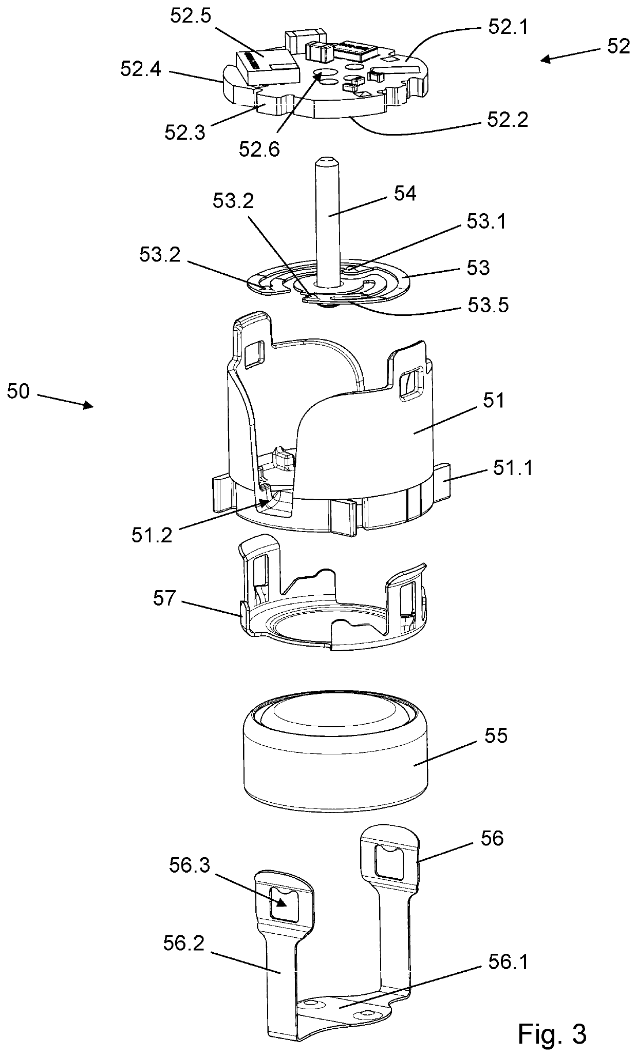
[0065]FIG. 8 is a perspective distal view of two sensor parts of another alternative rotary encoder system used in a sensor module according to the invention. Similarly to the previous embodiments the sensor parts comprise a wiper 253 and a PCB assembly 252 held in mutual position by the piston rod connector 54. The geometrical configuration of the PCB assembly 252 as well as its interaction with other components of the sensor module is identical to that of the formerly described PCB assembly 52. Particularly, the PCB assembly 252 comprises a rigid support sheet 252.4 having a proximal surface 252.1 which carries various electronic components 252.5, including a processor, and a distal surface 252.2 on which is disposed a plurality of electrically conductive sensor areas.
first embodiment
[0066]However, contrary to the former embodiments the distal surface 252.2 carries 40 electrically conductive sensor areas arranged in a circular track pattern where every other sensor area constitutes a ground field 252.7 and every other sensor area constitutes a code field 252.8. A secondary ground connection is supplied via the spherical end 54.1 of the piston rod connector 54 being in contact with the (negative) battery connector 57, as described above in connection with the invention.
[0067]The wiper 253 is attached to the piston rod connector 54 and is adapted to sweep the 40 electrically conductive sensor areas as the piston rod 15 rotates during a dose expelling action (as described above). The wiper 253 has three flexible arms 253.5, each terminating in a contact point 253.2 which is adapted to galvanically connect with a ground field 252.7 or a code field 252.8, depending on the angular position of the wiper 253 relative to the PCB assembly 252. The three contact points 253...
fourth embodiment
[0068]FIG. 9 is a perspective distal view of two sensor parts of yet another alternative rotary encoder system used in a sensor module according to the invention. Like in the previous embodiments the sensor parts comprise a wiper 353 and a PCB assembly 352 held in mutual position by the piston rod connector 54. The geometrical configuration of the PCB assembly 352 as well as its interaction with other components of the sensor module correspond to that of the formerly described PCB assembly 52. Particularly, the PCB assembly 352 comprises a rigid support sheet 352.4 having a proximal surface 352.1 which carries various electronic components (not visible), including a processor, and a distal surface 352.2 on which is disposed a plurality of electrically conductive sensor areas. The plurality of electrically conductive sensor areas comprises a circular ground track 352.7 and a circular code track 352.9 formed of 72 individual code fields 352.8 which are arranged side by side.
[0069]The ...
PUM
 Abstract
Description
Claims
Application Information
 - R&D
- Intellectual Property
- Life Sciences
- Materials
- Tech Scout
- Unparalleled Data Quality
- Higher Quality Content
- 60% Fewer Hallucinations
Browse by: Latest US Patents, China's latest patents, Technical Efficacy Thesaurus, Application Domain, Technology Topic, Popular Technical Reports.
© 2025 PatSnap. All rights reserved.Legal|Privacy policy|Modern Slavery Act Transparency Statement|Sitemap|About US| Contact US: help@patsnap.com


