Microfluidic systems, pumps, valves, fluidic chips thereof, and applications of same

a microfluidic system and fluid chip technology, applied in the field of microfluidic systems, can solve the problems of unaddressed need in the ar

Active Publication Date: 2022-11-17
VANDERBILT UNIV
View PDF18 Cites 3 Cited by
  • Summary
  • Abstract
  • Description
  • Claims
  • Application Information

AI Technical Summary

Problems solved by technology

Therefore, a heretofore unaddressed need exists in the art to address the aforementioned deficiencies and inadequacies.

Method used


Image

  • Microfluidic systems, pumps, valves, fluidic chips thereof, and applications of same
  • Microfluidic systems, pumps, valves, fluidic chips thereof, and applications of same
  • Microfluidic systems, pumps, valves, fluidic chips thereof, and applications of same

Examples


Embodiment Construction

[0032]The invention will now be described more fully hereinafter with reference to the accompanying drawings, in which exemplary embodiments of the invention are shown. The invention may, however, be embodied in many different forms and should not be construed as limited to the embodiments set forth herein. Rather, these embodiments are provided so that this disclosure will be thorough and complete, and will fully convey the scope of the invention to those skilled in the art. Like reference numerals refer to like elements throughout.

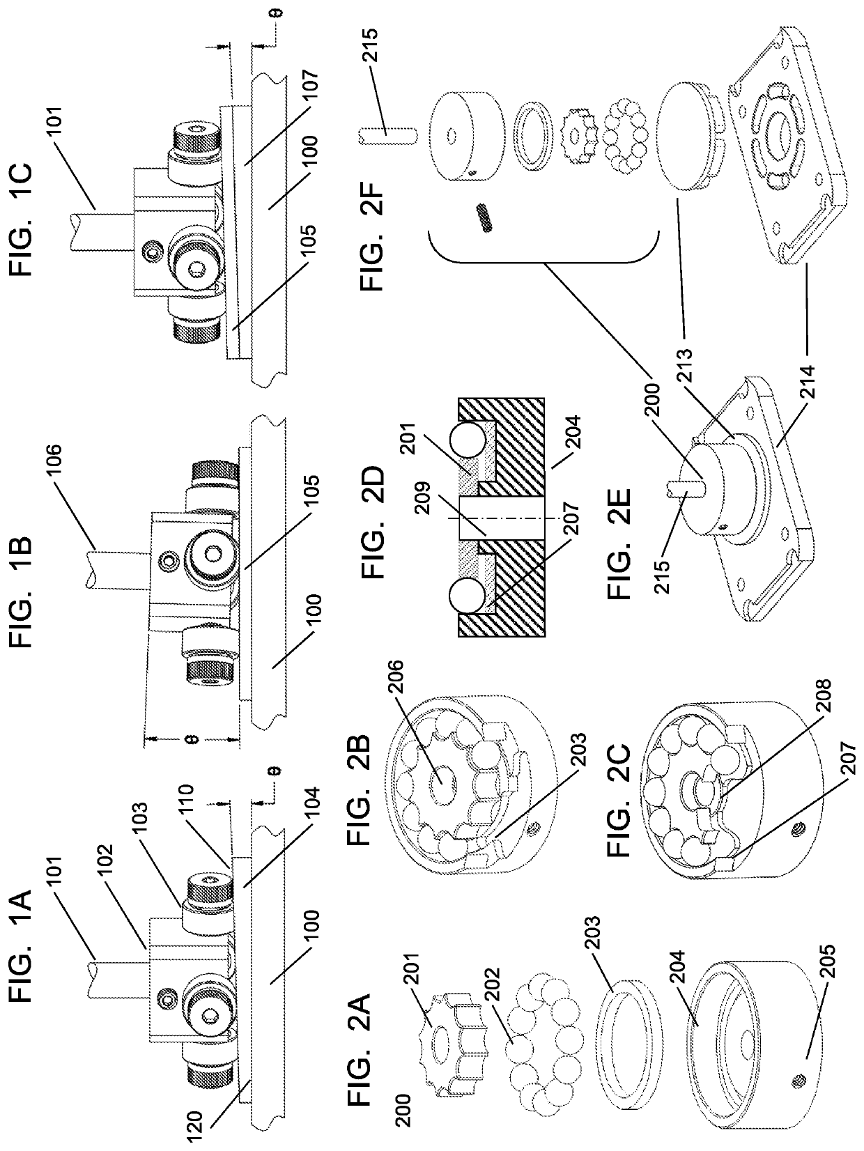
[0033]One aspect of the present invention relates to a microfluidic system, which is used as a tilted-rotor or actuator rotary peristaltic pump. FIGS. 1A-1C show a tilted actuator pump according to certain embodiments of the invention. Specifically, FIG. 1A shows a substantially vertical motor shaft 101 inserted into a pump actuator 102 that moves the rollers 103 to compress a wedge-shaped fluidic chip 104 with contacting surface 110 and fluidic surface ...


PUM


Abstract

Microfluidic systems, pumps, valves and applications of the same are provided. The microfluidic system may be a pump or a valve having a fluidic chip and an actuator controlling the opening and closing of the fluidic channel in the fluidic chip. The actuator may be disposed to tilt from the fluidic chip, forming a tilted-rotor peristaltic pump. Alternatively, the actuator may be a rolling ball actuator, and different fluidic chips may be used in different applications. For example, the fluidic chip may be a spiral pump chip having spiral channels, a rotary peristaltic pump chip having multiple output channels, or a multi-port valve chip having one port interconnected with multiple different ports. An analytical valve chip may switchably interconnect bioreactor and rinse/calibration input channels to sensor and waste output channels. The actuator of a random-access valve can move from one valve position to another without opening or closing intermediate ones.

Description

CROSS-REFERENCE TO RELATED PATENT APPLICATIONS[0001]This application claims priority to and the benefit of U.S. Provisional Patent Application Ser. No. 62 / 868,303, filed Jun. 28, 2019. This application is also a continuation-in-part application of PCT Application Serial Nos. PCT / US2019 / 047190, PCT / US2019 / 047307 and PCT / US2019 / 047324, all filed Aug. 20, 2019. Each of the above-identified applications is incorporated herein by reference in its entirety.STATEMENT AS TO RIGHTS UNDER FEDERALLY-SPONSORED RESEARCH[0002]This invention was made with government support under Grant Nos. 5UG3TR002097-02, U01CA202229 and HHSN271201700044C awarded by the National Institutes of Health, Grant No. 83573601 awarded by the U. S. Environmental Protection Agency, Grant No. 2017-17081500003 awarded by the Intelligence Advanced Research Projects Activity, and Grant No. CBMXCEL-XL1-2-001 awarded by the Defense Threat Reduction Agency through Subcontract 468746 by Los Alamos National Laboratory (LANL). The ...

Claims


Application Information

Patent Timeline
Patent Type & Authority Applications(United States)
IPC IPC(8): B01L3/00
CPCB01L3/502738B01L2300/0627B01L2300/123B01L2400/0644B01L3/50273B01L2400/0481F04B43/1261F16K11/163
Inventor REISERER, RONALD S.SCHAFFER, DAVID K.SAMSON, PHILIP C.MARKOV, DMITRY A.GEUY, MICHAELMCCAWLEY, LISA J.WIKSWO, JOHN P.
Owner VANDERBILT UNIV
Why Eureka
Try Eureka