Lubrication Distribution System

a distribution system and lubrication technology, applied in the direction of gearing details, belts/chains/gears, gear lubrication/cooling, etc., can solve the problems of limiting or prohibiting the addition or accommodation of a pump or other structure, the inability of the pump to precisely direct lubricant where it is needed, and the inability to integrate a pump into an existing mechanical system to move lubricant through the system and make it available for rotation and other system

Active Publication Date: 2022-11-17
BOREALIS TECH LTD
View PDF2 Cites 0 Cited by
  • Summary
  • Abstract
  • Description
  • Claims
  • Application Information

AI Technical Summary

Benefits of technology

[0006]It is an object of the present invention, therefore, to provide a lubrication distribution system for mechanical systems that have rotating components and tight clearances requiring the precise application of lubricant and optimal component lubrication during system operation.

Problems solved by technology

Providing a consistent supply of lubricant to component parts of mechanical systems, particularly mechanical systems with rotating components, and ensuring that the lubricant is moved into and through the system so that it is optimally and precisely distributed as required for the mechanical system to function presents challenges.
Integrating a pump into an existing mechanical system to move lubricant through the system and make it available for rotating and other system components may not be possible due to design constraints.
Further, required clearances and available space in a mechanical system may limit or prohibit the addition or accommodation of a pump or other structure that precisely directs lubricant where needed to moving and other system components.
Even if a lubricant pump able to provide an optimal supply of lubricant could be incorporated into an existing mechanical system, such a pump may not be capable of precisely directing lubricant where it is needed.
In addition, integrating a pump into an existing mechanical system may not avoid parasitic losses.
Achieving optimal and precise lubrication of mechanical systems with rotating components, for example gearboxes, transmissions, and the like, may present specific challenges.
The foregoing systems tend to be relatively complex, however, and may be difficult to install in an existing mechanical system to achieve an optimal lubricant flow or the precise distribution of lubricant.
This arrangement may waste lubricant and may not evenly spread lubricant through the system or precisely direct lubricant to bearings and other structures or rotating components that require lubrication.
The volume required to receive lubricant within the seal ring requires the seal ring to have a height that is not optimum, particularly in a mechanical system with tight clearances.
This may lead to lubricant slugging, increasing friction during rotation of the seal ring and creating operational problems in a gearbox or other mechanical system with rotating components.

Method used


Image

  • Lubrication Distribution System
  • Lubrication Distribution System
  • Lubrication Distribution System

Examples


Embodiment Construction

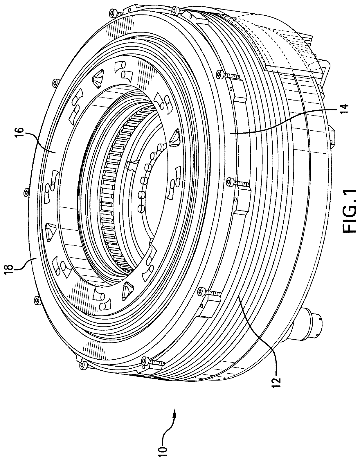
[0025]The lubrication distribution system of the present invention is designed to move lubricant smoothly and evenly through mechanical systems with rotating and other components that have tight clearances and little, if any, space to accommodate added structures for lubrication distribution. Components of the present system should fit within available tight clearances of a mechanical system and may be designed to be formed from existing system components that have been modified as described herein. The components may also be separate structures added to the system. While the lubrication distribution system of the present invention will be described in a gearbox application, it is contemplated that the present lubrication distribution system may also be effectively employed with other mechanical systems that have rotating components requiring precise lubrication.

[0026]The terms “lubricant” and “oil” are used interchangeably to refer to fluids used as lubricants. The term “lubricatio...


PUM


Abstract

A lubrication distribution system is provided for mechanical systems, including gearboxes, to evenly and precisely apply lubricant to system structures during operation. The system includes a rotating lubrication distribution component that functions both to pump and to precisely direct lubricant. Machined locator elements enable accurate positioning of the rotating lubrication distribution component within the system. A plurality of lateral ports and surface features in the rotating lubrication distribution component receive and distribute lubricant transferred during rotation from one or more lubricant collection components with profiled lubricant transfer elements that enables collection of lubricant from eddies produced by profiles of the lubricant transfer elements during rotation of the rotating lubrication distribution component. Collected lubricant is directed into the rotating lubrication distribution component ports and distributed evenly and precisely to mechanical system or gearbox structures requiring lubrication. An existing gearbox thrust bearing may be modified to receive and precisely distribute lubricant.

Description

TECHNICAL FIELD[0001]The present invention relates generally to systems and methods for lubrication of mechanical systems and specifically to a system and method that ensures optimal and precise distribution of lubricant during operation of a mechanical system with rotating components.BACKGROUND OF THE INVENTION[0002]Providing a consistent supply of lubricant to component parts of mechanical systems, particularly mechanical systems with rotating components, and ensuring that the lubricant is moved into and through the system so that it is optimally and precisely distributed as required for the mechanical system to function presents challenges. Integrating a pump into an existing mechanical system to move lubricant through the system and make it available for rotating and other system components may not be possible due to design constraints. Further, required clearances and available space in a mechanical system may limit or prohibit the addition or accommodation of a pump or other s...

Claims


Application Information

Patent Timeline
Patent Type & Authority Applications(United States)
IPC IPC(8): F16H57/04
CPCF16H57/0479F16H57/0427F16H57/0434F16H57/0428F16H57/0486
Inventor ANDERSON, ROBERT W.ROTENBERG, YONATANGREEN, SHAWN
Owner BOREALIS TECH LTD
Why Eureka
Try Eureka