Process and plant for manufacturing a composite plastic structure, for example a floor covering

a technology for manufacturing plants and composite plastics, which is applied in the direction of coatings, microwave heating, electrical appliances, etc., can solve the problems of significant deplasticization of the plastic layer or plastic layer, significant loss of plasticizing agents, and the deplasticization of the composite plastic structure or the floor covering. to the detriment of the required properties

Inactive Publication Date: 2000-01-11
GERFLOR
View PDF10 Cites 10 Cited by
  • Summary
  • Abstract
  • Description
  • Claims
  • Application Information

AI Technical Summary

Problems solved by technology

With plastisol-gelling ovens having infrared burners, it is found that there is a significant loss of plasticizing agents, these as it were therefore evaporating in the oven, and therefore there is a significant deplasticization of the layer or layers of plastic, and consequently of the composite plastic structure or of the floor covering.
This deplasticization is to the detriment of the required properties, and in particular makes the plastic much less flexible, or even brittle, which is unacceptable for a floor covering.

Method used


Image

  • Process and plant for manufacturing a composite plastic structure, for example a floor covering

Examples


example 2

This example starts with the intermediate product obtained according to Example 1.

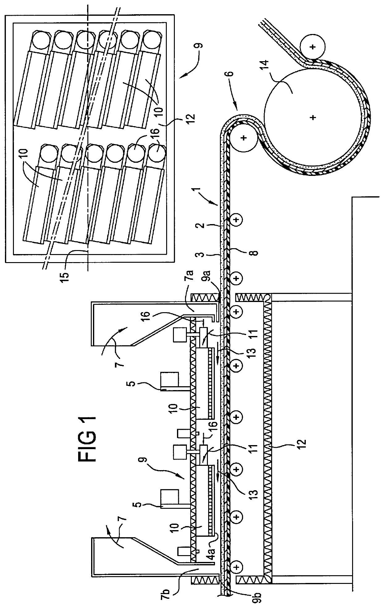
Next, a smoothing plastisol, according to a composition D, is applied on the reverse side of the glass web in an amount of 300 g / m.sup.2. The assembly is then gelled in the oven 9.

The temperature of the injected air 7 is 170.+-.5.degree. C. The temperature of the transporting means 8 is 150.+-.5.degree. C. in the inlet region and 160.+-.5.degree. C. in the outlet region. The run speed of the means 8 is 20 m / min. The thickness of the reverse-side layer deposited is 1.3 mm.

The gelled reverse-side layer has a beautiful appearance and is very uniform with good mechanical properties. The yellowness index measured as previously is less than 0.2 points.

example 3

This example starts from the intermediate product obtained according to Example 1.

A comfort foam plastisol, according to composition E, is then applied using a doctor in an amount of 395 g / m.sup.2.

The temperature of the inlet air 7 is 195.+-.5.degree. C. The temperature of the transporting means 8 is 174.+-.4.degree. C. in the inlet region and 203.+-.3.degree. C. in the outlet region. The run speed of the means 8 is 8 m / min. The thickness of the foam plastisol deposited is 1.33 mm after gelling. The deviation, with respect to this average thickness, does not exceed 0.1 mm in the machine and cross directions. The yellowness index measured as previously is less than 0.2 points.

The elongation values measured on the floor covering are 70.+-.10% compared to 35.+-.10% when the foam plastisol is expanded in a conventional gelling oven.

example 4

This example starts from the intermediate product obtained according to Example 1.

A mechanically foamed plastisol, having the composition F, is applied using a doctor in an amount of 870 g / m.sup.2. The expression "mechanical foam" means any foam obtained by mechanical means, for example by agitation, i.e. without the addition of chemical foaming agents. The assembly is then gelled in the oven 9, the incoming air 7 having a temperature of 190.+-.5.degree. C. The temperature of the means 8 is 175.+-.5.degree. C. in the inlet region and 195.+-.5.degree. C. in the outlet region. The run speed of the means 8 is 6.5 m / min. The thickness of the plastic deposited is 1.5 mm. The deviation with respect to this average thickness does not exceed 0.08 mm in the machine and cross directions.


PUM

PropertyMeasurementUnit
yellowness indexaaaaaaaaaa
lengthaaaaaaaaaa
lengthaaaaaaaaaa

Abstract

Process for manufacturing a flat composite plastic structure, for example a floor covering, comprising a textile web and at least one layer of a plastic, for example a polyvinyl chloride, on the reverse side or on the top side, which impregnates the textile web, according to which process: a) the textile web is made available, b) a plastisol is made available, c) the textile web is coated with a layer of plastisol, d) a radiant surface is obtained by combustion of a combustible gas in contact with a porous structure, e) the layer of plastisol is heated, using the radiant surface, in order to remove the volatile organic fraction of the coated layer and to cause the plastisol to gel, wherein the combustion of the combustible gas takes place under flameless, catalytic conditions.

Description

The present invention relates to the manufacture or production of any composite plastic structure, for example in the form of a sheet or slab, this structure comprising, in general, a strong textile web, giving the plastic structure its cohesion and strength, and at least one layer of a plastic, on the top side and / or reverse side, which impregnates the textile web. The latter comprises one or more yarns, or fibers, for example made of glass, which are organized and assembled with respect to one another in the form of a woven fabric or of a nonwoven. The plastic, which is thermoformable, may be any conventional plastic, such as polyvinyl chloride, chosen and formulated depending on the function of the layer of plastic, and / or on the use of the composite plastic structure.By way of nonlimiting example, the invention will be introduced, defined, described and explained with reference to the manufacture of a floor covering.DESCRIPTION OF THE PRIOR ARTIt is known to manufacture floor co...

Claims


Application Information

Patent Timeline
Patent Type & Authority Patents(United States)
IPC IPC(8): B29C35/06B29C35/04B29C70/04B29C70/50D06N3/00D06N3/06
CPCB29C35/06B29C70/50D06N3/0077D06N3/06
Inventor BERENGER, DANIEL
Owner GERFLOR
Why Eureka
Try Eureka