Method and apparatus for microwave predistorter linearizer with electronic tuning

a technology of predistortion linearizer and electronic tuning, which is applied in the direction of amplifiers with semiconductor devices only, amplifiers with semiconductor devices/discharge tubes, amplifier modifications to reduce noise influence, etc., and can solve the problems of insufficient complex transfer characteristic, large predistortion linearizer circuits, and individual circuits each suffering from one or more undesirable characteristics

Inactive Publication Date: 2000-01-18
MACOM TECH SOLUTIONS HLDG INC
View PDF11 Cites 7 Cited by
  • Summary
  • Abstract
  • Description
  • Claims
  • Application Information

AI Technical Summary

Problems solved by technology

However, those circuits each suffer from one or more undesirable characteristics.
For example, certain predistortion linearizer circuits are too large because of their complexity.
Other predistortion linearizers, while not as large, do not provide a sufficiently complex transfer characteristic to yield the linearized output at the high power amplifier that is desired.
In general, predistortion linearizers have not been flexible in their gain and phase response, being incapable of adjusting to changing conditions of operation to maintain optimum performance characteristics.

Method used


Image

  • Method and apparatus for microwave predistorter linearizer with electronic tuning
  • Method and apparatus for microwave predistorter linearizer with electronic tuning
  • Method and apparatus for microwave predistorter linearizer with electronic tuning

Examples


Embodiment Construction

Illustrative embodiments of the invention are described below. In the interest of clarity, not all features of an actual implementation are described in this specification. It will of course be appreciated that in the development of any such actual embodiment, numerous implementation-specific decisions must be made to achieve the developers' specific goals, such as compliance with system-related and business-related constraints, which will vary from one implementation to another. Moreover, it will be appreciated that such a development effort might be complex and time-consuming, but would nevertheless be a routine undertaking for those of ordinary skill in the art having the benefit of this disclosure.

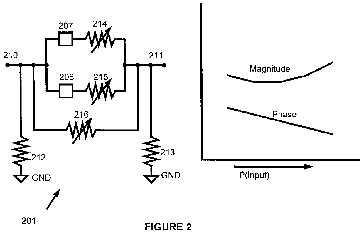
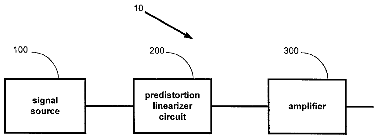
FIG. 1 shows a block diagram of a portion of an amplifier system 10 in which a predistortion linearizer circuit 200 has been inserted in a signal path between a signal source 100 and an amplifier 300. In processing a signal, the amplifier 300 will typically introduce magnitude and phas...


PUM


Abstract

A predistorter linearizer includes a magnitude distorter and a phase distorter, each including variability to provide a desired magnitude characteristic and phase characteristic. The method comprises adjusting a circuit to provide a desired magnitude characteristic and adjusting the circuit to provide a desired phase characteristic. A signal is modified using the desired magnitude and phase characteristics to produce a signal for amplification. The modification of the signal is offset by any modification resulting from the amplification, resulting in a more linearized amplifier output.

Description

1. Field of the InventionThis invention relates generally to a predistortion linearizer circuit useful for altering a signal prior to its input to a power amplifier in order to better linearize the output of the amplifier, and, more particularly, to a predistortion linearizer circuit with electronic tuning to linearize the power amplifier output.2. Description of the Related ArtHigh power amplifiers are routinely employed in many applications to amplify a signal to a power level sufficient for its intended transmission. For example, high power amplifiers are commonly employed in base station applications to amplify a signal for transmission. Solid state power amplifiers and traveling wave tube amplifiers are just two examples of high power amplifiers that have been used in these applications.Although these high power amplifiers impart sufficient gain to the amplified signal such that the signal may be transmitted along its intended path, the gain through the amplifier is typically n...

Claims


Application Information

Patent Timeline
Patent Type & Authority Patents(United States)
IPC IPC(8): H03F1/32
CPCH03F1/3276
Inventor ARELL, THOMAS WILLIAM
Owner MACOM TECH SOLUTIONS HLDG INC
Why Eureka
Try Eureka