Self-powered current monitor

a current monitor and self-powered technology, applied in the direction of instruments, electric devices, measurement using digital techniques, etc., can solve the problems of no means to provide historical data or detailed information, adverse effects on current sensing accuracy, and none of them fulfill the objects of the self-powered current monitor

Inactive Publication Date: 2000-01-25
EDEL THOMAS G
View PDF6 Cites 180 Cited by
  • Summary
  • Abstract
  • Description
  • Claims
  • Application Information

AI Technical Summary

Problems solved by technology

This ammeter provides a digital display, but has no means to provide historical data or detailed information beyond indication of present current magnitude.
However, current-sensing accuracy is adversely affected by high secondary burden on the current transformers.
However, none of them fulfill the objects of the self-powered current monitor invention described herein.

Method used


Image

  • Self-powered current monitor
  • Self-powered current monitor
  • Self-powered current monitor

Examples


Embodiment Construction

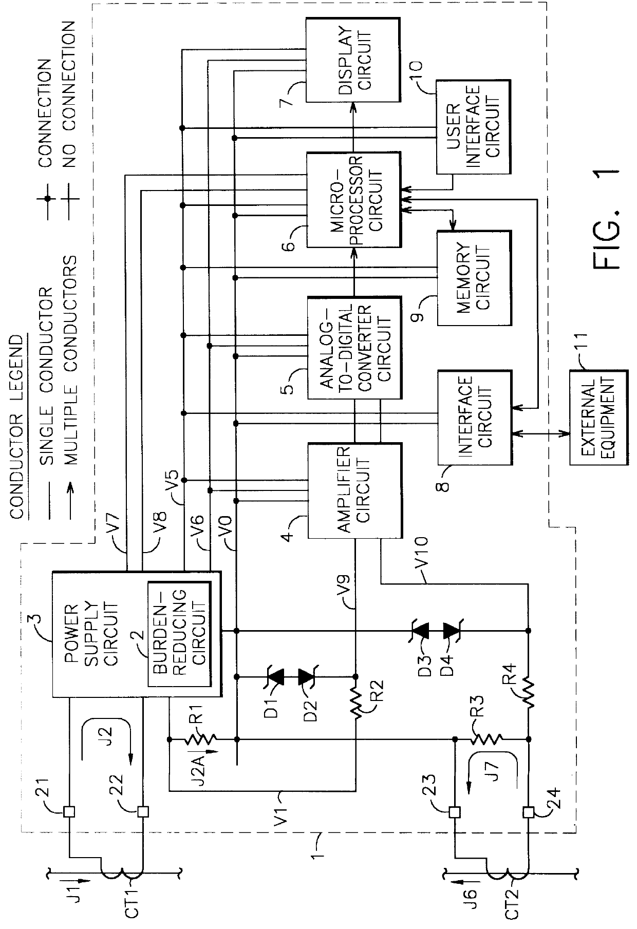
FIG. 1 shows a block diagram illustrating the general configuration of the self-powered current monitor 1. A power supply circuit 3 derives power from an input current J2 and provides regulated d-c (direct-current) power to other circuits. A burden-reducing circuit 2 may be included as part of power supply circuit 3. Power supply circuit 3 and burden-reducing circuit 2 are shown in more detail in subsequent figures and are discussed further in the discussion relating to those figures.

A current transformer CT1 acts as a current source to generate input current J2. Current transformer CT1 is external to current monitor 1 and may be almost any type of current transformer (or other current source), but will normally be a toroidal type or split-core type of current transformer installed around a current-carrying conductor. An a-c system current J1 flows in the current-carrying conductor as part of a larger electric power system. A-c system current J1 causes input current J2 to flow by th...


PUM


Abstract

A self-powered current monitor for monitoring current in electric power systems. Various data relating to input currents may be displayed, such as current magnitude, current demand, and harmonics levels. Operating power is derived from one or more of the input currents. The power supply configuration may include a burden-reducing means to reduce the burden on input current sources during sampling of the input currents. The self-powered current monitor (1) includes a power supply section (3), input resistors (R1 and R3), an analog-to-digital converter circuit (5), a microprocessor circuit (6), a memory circuit (9), and a display circuit (7). Optional features include a burden-reducing circuit (2), input circuit protective elements (D1, D2, D3, D4, R2, and R4), an amplifier circuit (4), a user interface circuit (10), and an interface circuit (8) for communication to other equipment.

Description

Field of the InventionThis invention relates to monitoring electric current in electric power systems, and more particularly to a current monitor which derives its operating power from one or more electric current inputs.GeneralAn electric current flowing in a conductor causes heating of the conductor. Electric energy is converted to thermal energy everywhere that electric current is flowing (except in specialized equipment utilizing superconducting materials). Generally speaking, the amount of thermal energy produced is proportional to the resistance of the conductor and to the square of the current magnitude. Electric heating equipment uses this principle to produce heat for beneficial purposes. However, this same principle is also at work throughout electric power systems to produce undesirable heat and related energy loss.Most electric power system components have limited current ratings because of this heating effect of electric current in conductors. Proper design and operatio...

Claims


Application Information

Patent Timeline
Patent Type & Authority Patents(United States)
IPC IPC(8): G01R19/25G01R1/20G01R1/00G01R13/00G01R13/02
CPCG01R19/2513G01R1/20G01R13/02
Inventor EDEL, THOMAS G.
Owner EDEL THOMAS G
Why Eureka
Try Eureka