

Female terminal fitting
- Summary
- Abstract
- Description
- Claims
- Application Information
AI Technical Summary
Benefits of technology
Problems solved by technology
Method used
Image

Examples
first embodiment
the present invention relating to a female terminal fitting is explained hereinbelow, with reference to FIGS. 1 to 7.
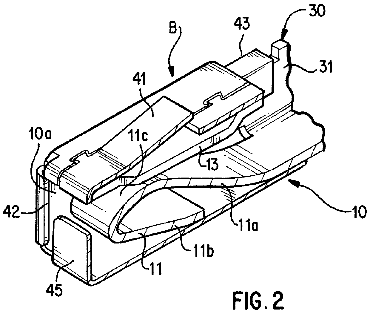
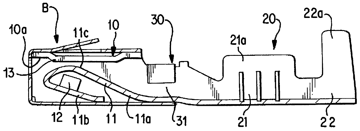
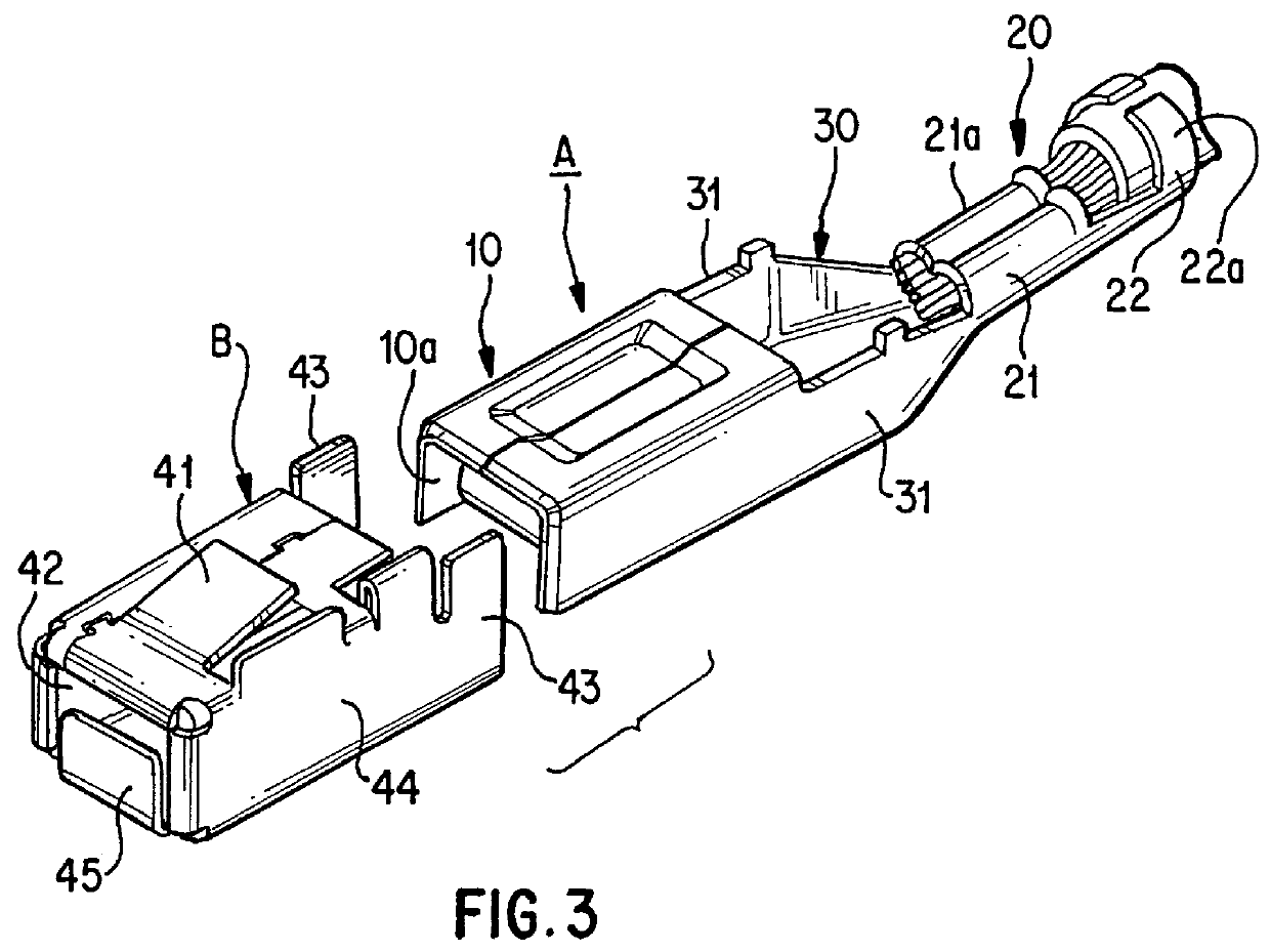
As shown in FIG. 3, a female terminal fitting of the present embodiment comprises a terminal main body A made from an electrically conducting metal sheet (for example, a thin copper alloy) that has been bent, and a protecting cover B that covers the terminal main body A.
The terminal main body A is configured so as to be provided with an insertion member 10 into which a corresponding male terminal fitting C (see FIG. 5) is inserted, and a barrel member 20 connected to the insertion member 10 via a connecting member 30, the terminal of an electric wire being connected by crimping thereto. The barrel member 20 comprises a wire barrel 21 that crimps a wire core of an electric wire, and an insulation barrel 22, connecting to the posterior side of the wire barrel 21, that crimps a covered portion of the electric wire. The barrels 21 and 22 protrude conventionally upwards as...
second embodiment
A second embodiment is shown in FIG. 8. The lower side of a supporting member 11b of an elastic contact 11 has a pushing member 61 formed on the base face of a protecting cover B. Since the configuration of the other parts are the same as in the first embodiment, the same numbers are accorded to parts having the same configuration as in the first embodiment, and an explanation thereof omitted.
The pushing member 61 is formed by pressing in the lower face of the protecting cover B, the supporting member 11b being supported in the direction opposite to its bending direction when a male terminal fitting C is inserted.
In the case where the male terminal fitting C is inserted at an angle, or if it is manipulated during insertion, the supporting member 11b is pushed with an excessive force against the base face of the protecting cover B. More specifically, if the pushing member 61 of the present embodiment is not provided, then, as shown in FIG. 7, approximately the entire supporting membe...
third embodiment
A third embodiment is shown in FIGS. 9 to 11. The lower edge of an insertion member 70 has its left and right side walls 70a folded inwards, forming folded over members 71. When a contact 11 is cut out from the base plate, cuts 72 are formed slightly inwards with respect to the left and right side edges (the upper and lower edges in FIG. 11). The lower edge of the supporting member 11 folded over from the anterior side downwards is in approximately the same location as the folded over member 71 (see FIG. 12), and is set so as not to protrude downwards from the base face of the insertion member 70. The contacting member 11c has a protruding member 11d formed on the upper face thereof by pressing, and is arranged to make contact in a reliable manner with the male terminal fitting C (see FIG. 5). The configuration of the other parts being the same as in the first embodiment, the same numbers are accorded to parts having the same configuration as in the first embodiment, and an explanat...
PUM
 Abstract
Description
Claims
Application Information